- 您的位置:
- 标准下载网 >>
- 标准分类 >>
- 石油化工行业标准(SH) >>
- SH 3076-1996 石油化工企业建筑物结构设计规范
标准号:
SH 3076-1996
标准名称:
石油化工企业建筑物结构设计规范
标准类别:
石油化工行业标准(SH)
标准状态:
现行-
发布日期:
1996-03-14 -
实施日期:
1996-09-01 出版语种:
简体中文下载格式:
.rar.pdf下载大小:
190.84 KB
替代情况:
SHJ 1079-1986
点击下载
标准简介:
标准下载解压密码:www.bzxz.net
本规范适用于石油化工企业新建建筑物的结构设计,改扩建工程可参照执行。 SH 3076-1996 石油化工企业建筑物结构设计规范 SH3076-1996
部分标准内容:
STANDARDSEORINDUSTRIESOE
THE PEOPLE'SREPUBLIC OF CHINASH
SH3076-96
CODE FOR DESIGN OF BUILDING STRUCTURESOFPETROCHEMICALENTERPRISES
(石油化工企业建筑物结构设计规范)Issuedon1996-03-14
Implemented as of 1996-09-01IssuedbyChinaNational Petrochemical Corporation1. General Provisions
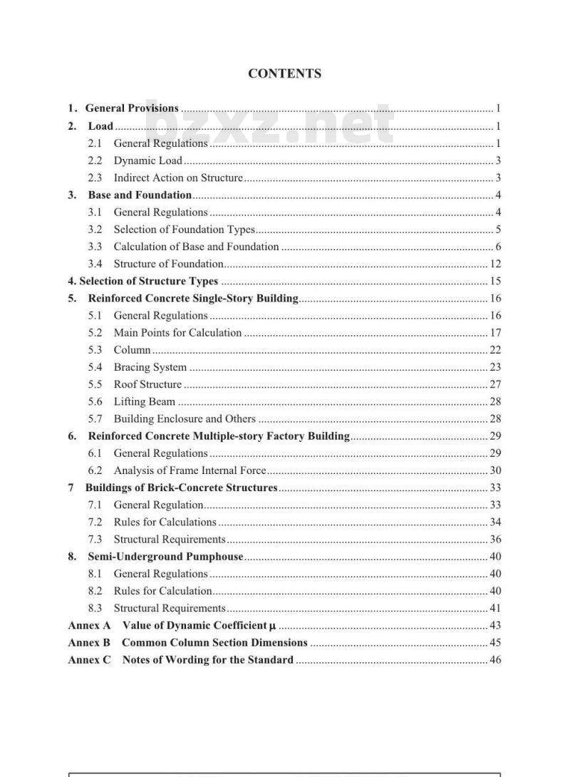
2.1 General Regulations.
2.2DynamicLoad
2.3Indirect Action on Structure.3.BaseandFoundation.
3.1 General Regulations..
CONTENTS
3.2SelectionofFoundationTypes.3.3Calculation of Base and Foundation..3.4Structure ofFoundation.
4.Selection of StructureTypes5.Reinforced Concrete Single-StoryBuilding5.1 General Regulations
5.2MainPoints forCalculation.5.3
5.4BracingSystem
5.5RoofStructure
5.6LiftingBeam
5.7BuildingEnclosureandOthersReinforced Concrete Multiple-story Factory Building.6.
6.1 General Regulations...
6.2Analysis ofFrame Internal Force..7Buildings of Brick-Concrete Structures.7.1 General Regulation..
7.2Rules for Calculations
7.3 Structural Requirements.Semi-Underground Pumphouse...8.
8.1 General Regulations...
8.2Rules for Calculation.
8.3Structural Requirements.
AnnexAValueofDynamicCoefficientμAnnexBCommonColumnSectionDimensionsAnnex CNotes of Wording for the Standard4
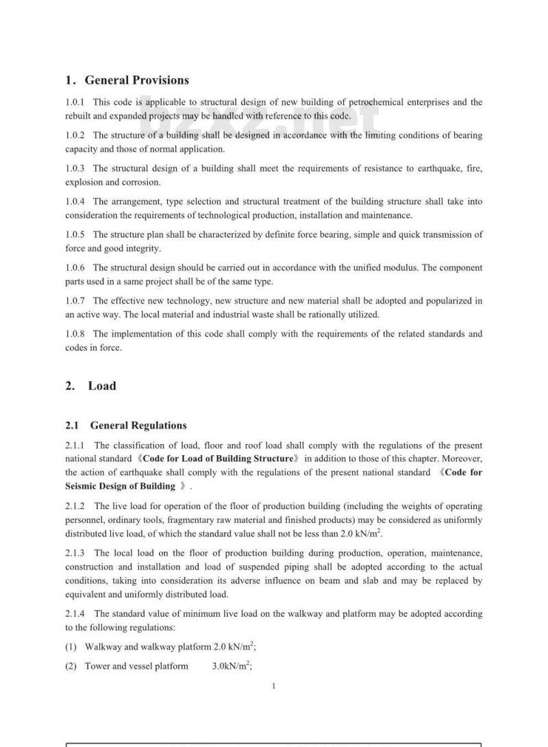
1.GeneralProvisions
1.o.1This code is applicable to structural design of new building of petrochemical enterprises and therebuilt and expanded projects may be handled with reference to this code.1.0.2The structure of a building shall be designed in accordance with the limiting conditions of bearingcapacity and those of normal application.1.0.3The structural design of a building shall meet the requirements of resistance to earthquake, fire,explosion and corrosion.
1.0.4The arrangement, type selection and structural treatment of the building structure shall take intoconsideration the requirements of technological production, installation and maintenance.1.o.5The structure plan shall be characterized by definite forcebearing,simple and quick transmission offorce and good integrity.
1.0.6The structural design should be carried out in accordance with the unified modulus. The componentpartsused ina sameproject shall beof thesametype.1.0.7 The effective new technology, new structure and new material shall be adopted and popularized inan active way.The local material and industrial waste shall be rationally utilized.1.0.8The implementation of this code shall comply with the requirements of the related standards andcodes inforce.
2.1GeneralRegulations
2.1.1The classification of load, floor and roof load shall comply with the regulations of the presentnational standard 《Code for Load of Building Structure》 in addition to those of this chapter.Moreover,the action of earthquake shall complywith the regulations of thepresent national standard《CodeforSeismicDesignofBuilding》
2.1.2The live load for operation of the floor of production building (including the weights of operatingpersonnel, ordinary tools, fragmentary raw material and finished products) may be considered as uniformlydistributed liveload,ofwhichthestandardvalueshallnotbelessthan2.kN/m22.1.3Thelocal load on thefloorof productionbuildingduringproduction,operation,maintenance,construction and installation and load of suspended piping shall be adopted according to the actualconditions, taking into consideration its adverse influence on beam and slab and may be replaced byequivalentanduniformlydistributedload.2.1.4The standard value of minimum live load on the walkway and platform maybe adopted accordingtothefollowingregulations:
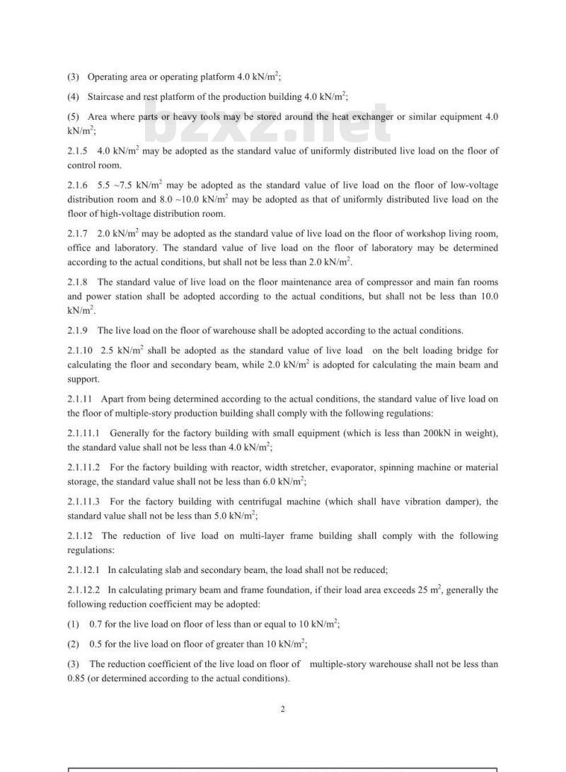
(1)Walkwayandwalkwayplatform2.0kN/m2(2)Towerand vessel platform
(3)Operatingareaoroperatingplatform4.0kN/m2;(4) Staircase and rest platform of the production building 4.0 kN/m2;(5) Area where parts or heavy tools may be stored around the heat exchanger or similar equipment 4.0kN/m2;
2.1.54.0kN/mmaybeadopted as the standard value ofuniformlydistributed live load onthefloor ofcontrolroom
2.1.65.5~7.5kN/mmaybe adopted as the standard valueof live load on thefloor of low-voltagedistribution room and 8.0 ~10.0 kN/m2 may be adopted as that of uniformly distributed live load on thefloorof high-voltagedistributionroom.2.1.72.0 kN/m may be adopted as the standard value of live load on the floor of workshop living room,office and laboratory.The standard value of live load on thefloor of laboratory maybedeterminedaccording to the actual conditions, but shall not be less than 2.0 kN/m.2.1.8The standard valueof liveload on thefloor maintenance areaof compressor and mainfan roomsand power station shall be adopted according to the actual conditions, but shall not be less than 1o.0kN/m2.
2.1.9The live load on the floor of warehouse shall be adopted according to the actual conditions2.1.102.5 kN/m2shall be adopted as the standard value of live loadon the belt loading bridge forcalculating the floor and secondary beam, while 2.0 kN/m is adopted for calculating the main beam andsupport.
2.1.11 Apart from being determined according to the actual conditions, the standard value of live load onthe floorof multiple-storyproduction building shall complywith thefollowingregulations:2.1.11.1 Generally for the factory building with small equipment (which is less than 200kN in weight),the standard value shall not be less than 4.0kN/m;2.1.11.2For the factory building with reactor, width stretcher, evaporator, spinning machine or materialstorage, the standard value shall not be less than 6.0 kN/m;2.1.11.3For the factory building with centrifugal machine (which shall have vibration damper), thestandard valueshall notbelessthan5.0kN/m2;2.1.12The reduction of liveload on multi-layerframebuilding shall comply withthefollowingregulations:
2.1.12.1Incalculating slaband secondarybeam,theload shall notbereduced;2.1.12.2In calculating primary beam andframefoundation, iftheir load area exceeds25m2,generally thefollowing reduction coefficientmaybe adopted:(1)0.7for the live load on floor of less than or equal to10kN/m2;(2)0.5fortheliveload onfloorofgreaterthan10kN/m2;(3)The reduction coefficient of the live load on floor of multiple-story warehouse shall not be less than0.85 (ordetermined accordingtothe actual conditions).2
2.1.13For designing the platform railing, the standard value of horizontal thrust shall be 1.0 kN/m2whichactsonthetopofrailing.
The load of pile-upmaterial and equipment for production onground and load of land transport2.1.14
shallbedetermined according totheactual conditions2.1.15
In considering the dust load on roof, attention shall be paid to the influence of the adjacent area(including nearbyfactory)onthedust load ofthisbuilding2.2DynamicLoad
2.2.1 The power equipment (such as centrifugal machine, crusher, vibrating screen, extruder, reactor,evaporator, spinning machine, large-size ventilator and so on) installed on the floor should have vibrationisolator. The dynamic load parameters of different kinds of power equipment shall be supplied by themanufacturer.
2.2.2The dynamic load of structure shall be calculated and determined according to the specialregulations. A part of the power equipment may be statically calculated by multiplying the weight ofequipment by dynamic coefficient which is listed in Appendix A.With reliable experience, a part of powerequipment may be calculated according to the experienced method.The stationary equipment with driving device may be calculated by multiplying the weight of rotating partbydynamiccoefficient.
After taking appropriate measurefor vibration isolation, the dynamic load of the following equipment maynotbetaken intoconsideration (exceptforsteel platform).(1)Ordinaryequipmentofwhichthemotorpowerisnotgreaterthan1ookW;(2)Crusher,vibratingscreen and other equipmentof whichthe motorpower isnotgreaterthan75kW:(3)Forced draught fan of which the type is smaller than no. 10.2.2.3 Generally the dynamic coefficient for transporting,loading and unloading heavy weight may beadopted according to 1.1 ~ 1.2, only taking into consideration its dynamic action transmitted to the floorandbeam.
2.3IndirectActiononStructure2.3.1Actionoftemperature
2.3.1.1 For the equipment, vessel, reactor and piping in the process of production, the expansion,contraction and action of the component parts on structure due to the change of temperature shall be takeninto consideration;
2.3.1.2For the equipment subject to the influence of temperature in the process of production, thehorizontal action of the change of temperature on the top of foundation shall be taken into considerationand calculated according to the following formula:3
Fik=μGBk
Ftkstandardvalueof horizontalactiononthesupportingtop;μ Friction coefficient between supporting base plate and supporting surface of the equipmentwhich is 0.45 for concrete supporting surface and 0.3 for sheet steel supporting surface;GBkStandard value of equipment permanent load acting on this support under normaloperatingcondition.
2.3.2 Coring load ofheatexchangenThe foundation of heat exchanger shall take into consideration the horizontal load caused by coring duringmaintenance. This load acts on the axis of heat exchanger. If several heat exchangers are placed one onanother,onlythetopmost oneis calculated.Thehorizontal load caused by coring shall be calculatedaccordingtothefollowingformulaFbk=Gbk
WhereFbk—standardvalueof coring force(2.3.2)
Gbkstandard valuemeasuredby thebundleof cold-water exchange equipment.3.1
Base and Foundation
3.1GeneralRegulations
3.1.1The base and foundation shall be designed by adhering to the principles of suiting measures to localconditions and using local materials, according to the geological prospecting data and taking intoconsideration in a comprehensive way the body type of building, type of structure,load conditionexistence or nonexistence of basement, foundation of adjacent building, position and elevation ofunderground structure and different facilities, conditions for construction, requirementfor use, project costandotherfactors.
3.1.2The design of base and foundation of soft soil, wet and depressed loess, expanded soil and undenthe action of earthquake and mechanical dynamic load shall comply with the regulations of relatedstandard and code in force.
3.1.3All pits, caves,graves,wells and so forth within the range of influence of the building foundationshallbedisposed.
3.1.4In water-proof design, the elevation of water level of the building basement may be determinedaccordingtothefollowingprinciples:3.1.4.1For the basement with important electromechanical equipment which, in case of flooding,willexert great influence on the normal use of the building or cause heavy losses to it, the water-proof designshall be conducted according to the highest water level over the years in that area (the elevation of waterlevel shall include the stagnant water on the upper floor);3.1.4.2For the basement used as ordinary air-raid shelter, garage or warehouse which will not have greatinfluence in case of flooding, the elevation of its groundwater level may take the average value of the4
highest water level over the years and the highest water level in recent3 to 5 years (the elevation ofwaterlevel shallincludethestagnantwaterontheupperfloor).3.1.4.3In checking the bearing capacity of outer wall of the basement, the highest water level in recent 3to 5yearsmay be taken as the elevation of water level,not including the stagnant water on the upperfloor.3.2
Selectionof FoundationTypes
3.2.1 For the base and foundation of a building, natural base should generally be adopted. If the naturalbase cannot meet the requirements of design or is uneconomical, artificial base may be adopted.3.2.2Thetype selection offoundation with masonry structure shallcomplywith thefollowingprinciples:3.2.2.1 Rigid foundation should be used as the wall column foundation. If the base is soft and unevenwith a small bearing capacity and a foundation width of more than 2.0 m, flexible foundation withreinforced concrete under the wall should be adopted;3.2.2.2When the bearing wall foundation is no more than 1.8m in depth,flexible strip foundation shouldbe adopted.When it is 1.9~2.4 m in depth, flexible strip foundation or pier foundation and foundationbeam may be adopted.When it ismore than 2.4 m in depth with solid base, pier foundation and foundationbeam should be adopted;
3.2.2.3Whenthenon-bearingwall isnomorethan240mminthicknessand nomorethan4.0minheight, theground pad layer maybethickened without laying additionalfoundation.3.2.3If the framed structure has no basement and the standard value of the base bearing capacity isgreater than 130 kPa and even, priority should be given to single column foundation. When the standardvalue of the base bearing capacity is less than 130 kPa with small column space, heavy load or excessivedifference between column loads which may cause great relative settlement or great change incompressibilityof themain compressed layerof foundationand theadoption of single columnfoundationcannot meet the requirement of design, strip foundation with reinforced concrete under the column may beadopted.
When part of the column foundation of a building is more than 3.0 m in depth, short column foundationshould be adopted. If it is no more than 3.o m in depth or individual foundation is a bit deep, thefoundation pad layermaybethickened.3.2.4When the load of a building with framed structure is heavy and the base is soft and uneven,crosswisereinforcedconcretestripfoundationmaybeused.When this crosswise foundation still cannot meet the requirements of design or the basement used asair-raid shelter has water-proof requirement, raft reinforced concrete foundation or box foundation may beused.
3.2.5In the following cases, pile foundation may be used:3.2.5.1When the base is uneven or base on bearing stratum is soft and has better low-lying stratum andthe adoption of raft foundation is uneconomical;3.2.5.2For the importantbuildingwhichhas special requirement forbase in application and productiontechnology or has great pressure on bottom of foundation, when the settlement estimated by natural baseexceedstheallowablevalue;
3.2.5.3For the high-rise building, if the construction conditions do not allow to use deeply-embeddednaturalbaseoritisnotevidentlyeconomical;3.2.5.4When the additional stress of base between units of the building interacts on each other, causingexcessiveuneven settlement;
3.2.5.5When the use of pile foundation is economical because of a vast area of stacked material or thinlayer of soft soil under the foundation.3.3
Calculation of Base and Foundation3.3.1Whenthebottomareaofcolumnfoundationofa factorybuilding isdeterminedonthebasis of thebase bearing capacity, the design value of pressure on the foundation base shall be taken according to thefollowing regulations:
3.3.1.1For the column foundation of a factory building with a load of crane (not including crane formaintenance), the design value of pressure on the foundation base shall not be negative (see Fig. 3.3.1-1)and shall meettherequirements of thefollowingformula:ee=M/(N+G)
whereeeccentric load (m);
(3.3.1—1)
(3.3.1—2)
M bending moment acting on centroid of foundation base (kN ·m);N-vertical loadactingoncentroidoffoundationtop(kN);Gdead weight offoundation and soil (kN);Bfoundationwidth (m).
When bearing load of electric bridge crane and the design value of bearing capacity of foundation f<170kPa,theprofileofpressureonthefoundationbaseshallassumetrapezoidandPmin/Pmax>0.25.3.3.1.2For the column foundation of a factory building with a crane for maintenance but without load ofcrane, when the wind load combination is taken into consideration, the design value of the pressure onfoundation base is allowed to be negative (see Fig. 3.3.1.2) and shall meet the requirements of thefollowingformula:
Whene(3.3.1—3)
Whene=B/6
Fig.3.3.1—1Pressure on column foundation base with craneWhenB/6eFig.3.3.1—2Pressure on column foundation base without crane3.3.2The bilaterally and eccentrically-loaded column foundation shall be calculated according to thefollowingregulations:
3.3.2.1 The bilaterally and eccentrically-loaded column foundation, when meeting the following formula,maybe calculated according to the unilaterally and eccentrically loaded oneey/A≤0.2ex/B
where A short-edge width of foundation base (m);Blong-edgewidthof foundationbase (m);(3.3.2—1)
ex and eyeccentric value of foundation base axial force at long and short sides (m)3.3.2.2Wheney≤A/6and ex≤B/6,the pressure onfoundationbase shall takeinto consideration theinfluence of bending moments at the directions of X and Y. The bending moment at the cross section ofcolumn edgemaybeapproximatelycalculated accordingtoformulas(3.3.2—2and3):(B-b)(2A+a) P,
(A-a)\(2B+b)
(3.3.2-2)
(3.3.2-3)
aandbsizes of shortand long edges ofthecolumn respectivelywhere
PiandPri
maximumpressureonthecalculatedfoundationedgesP,
Fig.3.3.2—1Externalforcecalculated onthefoundationwithbilateral eccentricity3.3.2.3When thefoundation partially leaves the soil, the design value of foundationbase pressuremaybecalculatedaccordingtothefollowingformula:N+G
Pmax=0.35-
(3.3.2-4)
whereCxandCydistancesfromactingpointofvertical load to thenearestedges of foundationatXandYcoordinates,Cx·Cy≥0.125B·A
Fig.3.3.2—2Schematic diagram of bilaterally and eccentrically-loaded positions3.3.3The calculation of short-column cup-shaped foundation shall comply with the following regulations:8
3.3.3.1When the height H, of upper step of foundation is greater than H.+ t + 125 (mm), then it isdeemed as the short-column cup-shaped foundation (see Fig. 3.3.3—1);3.3.3.2When the short-column cup-shaped foundation complies with thefollowingformula, its influenceonthebentmaybeneglected (seeFig.3.3.3—2);A1/A2<1.1
Where:
column cap deflection caused when force is concentrated on the column cap action unit with thefoundationtop (orshort column base)as afixed end:Acolumn cap deflection caused when force is concentrated on the column cap actionunitwith the cupmouthtopasafixedend.
Fig.3.3.3—1Schematicdiagramof short-columncup-shapedfoundationCupmouth top
Short column bottom
Fig.3.3.3—2Analysis of influence of short column foundation on bent3.3.4The base reaction of reinforced concrete strip foundation under the column should be calculatedwith the solution of elastic foundation beam. When the foundation is of great plasticity and not too thick9
soil layer,the foundation bed coefficient method should be adopted.For the reference value of foundationbed coefficient see Table3.3.4.When the foundationmainly lies ona thick compressed soil layer ina stateofelasticdeformation,thesemi-infinite elastomermethod should be adopted.Whenthefoundationbeamishigherthan or equal to 1/6 of column space,it is assumed that the base reaction is distributed linearlyTable3.3.4Referencevalueof foundationbedcoefficientKNameof soil
Weak sludgesoil,organicofsoilClay,silty clay
Sandy soil
Gravelly soil
Loess,loesssiltyclay
State of soil
Soft plastic
Plastic
Hard plastic
MediumdensitybZxz.net
Density
Medium density
K(kN/m)
0.5×10⁴~1.0x10⁴
0.5x10⁴~2.0x10⁴
2.0x10⁴~4.0×10⁴
4.0x10⁴~10.0x10⁴
0.7x10⁴~1.5×10⁴
1.5×10*~2.5×10⁴
2.5×10*~4.0×10⁴
3.5×10~4.0×10⁴
4.0×10⁴~5.0x10⁴
3.3.5 Upstanding beam method is suitable for foundation beam with a ratio of rise to span of 1/4 ~ 1/6,even ground and no significant differential deformation. The internal force of beam may be calculatedaccording to the following method:3.3.5.1Accordingtothecalculatingmethod ofmultiple-spancontinuousbeam:()
The base reaction may be assumed to distribute in straight line (take a unit width b=1);P-6M
(3.3.5-1)
whereZN-resultantforceofvertical loads(kN);L-lengthoffoundationbeam(m);Msum ofvertical loads and theireccentricmomentto themomentatmid-pointoffoundation(2) For analysis of foundation beam internal force, the evaluated base reaction may be taken as theexternal load and the column footing as the support of upstanding continuous beam. When the calculatedresult cannot meet the static balance condition at the support, the unbalanced force may be used to adjustthe reaction, i. e. the unbalanced force is evenly distributed at both sides of the support within the range of1/3 of the span to form a new stepped reaction distribution, calculate the adjusted internal force, againcalculate the superimposition of results. Repeat the above procedures until the support reaction andunbalancedforceofcorrespondingcolumnloaddonotexceed2o%oftheload.10
小提示:此标准内容仅展示完整标准里的部分截取内容,若需要完整标准请到上方自行免费下载完整标准文档。
标准图片预览:
- 热门标准
- 石油化工行业标准(SH)
- SHS07007-2004 特殊仪表
- SH/T3055-2007 石油化工管架设计规范
- SH/T3151-2013 石油化工转子泵工程技术规范
- SH/T3530-2001 石油化工立式圆筒形钢制储罐施工工艺标准
- SH/T0605-2008 润滑油及添加剂中钼含量的测定 原子吸收光谱法
- SH/T0759-2005 内燃机油低温油泥和抗磨损性能评定法(程序ⅤE法)
- SH/T0338-1992 滚珠轴承润滑脂低温转矩测定法
- SH/T3120-2000 石油化工喷射式混合器设计规范
- SHBZ03-1995 过程用二进制逻辑图
- SHS02001-2004 催化裂化反应器再生器维护检修规程
- SHS03063-2004 透平膨胀机维护检修规程
- SH/T0761-2005 柴油机油性能评定法(MACK T-9法)
- SH/T0764-2005 柴油机喷嘴结焦试验方法(XUD-9法)
- SH/T0559-1993 柴油中硝酸烷基酯含量测定法(分光光度法)
- SH/T0749-2004 润滑油及添加剂中添加素含量测定法(电感耦合等离子体发射光谱法)
- 行业新闻
请牢记:“bzxz.net”即是“标准下载”四个汉字汉语拼音首字母与国际顶级域名“.net”的组合。 ©2025 标准下载网 www.bzxz.net 本站邮件:bzxznet@163.com
网站备案号:湘ICP备2025141790号-2
网站备案号:湘ICP备2025141790号-2