DIN 158-2
公制锥管外螺纹及配合的平行内螺纹 第2部分:量规和量规检验
DIN 158-2
Metric taper external and mating parallel internal screw threads Part 2: Gauges and gauging
标准信息
STANDARD INFORMATION- 标准编号
- DIN 158-2
- 所属分类
- DIN 德国标准
- 发布机构
- DIN
- 版本年份
- 1997
- 文件语言
- 英语
- 文件格式
- 文件页数
- 6 页
- 文件大小
- 3.25 MB
中文名称为参考译名,文件语言以原文为准。
· 更新:
标准简介
OVERVIEW中文简介
该标准规定了用于检验公制锥管外螺纹及其配合的平行内螺纹的量规系统。它详细说明了平行极限螺环规和锥管螺塞规的轮廓、尺寸、制造公差及检验方法,适用于DIN 158-1中规定的螺纹规格。
English summary
This standard specifies a gauging system for metric taper external threads and mating parallel internal threads as defined in DIN 158-1. It details the profiles, dimensions, manufacturing tolerances, and inspection methods for parallel limit screw ring gauges and taper screw check plugs.
以上为根据文件整理的内容简介。
相关标签
标准内容预览
DOCUMENT PREVIEWMetric taper external and mating parallel internal screw threads
Part 2: Gauges and gauging
ICS 17.040.30; 21.040.10
Descriptors: Metric taper external screw threads, parallel internal screw threads, gauges, gauging.
Metrisches kegelförmiges Außengewinde mit zugehörigem zylindrischem Innengewinde – Teil 2: Lehrensystem, Anwendung der Lehren, Berechnung der Lehrenmaße und Baumerkmale
In keeping with current practice in standards published by the International Organization for Standardization (ISO), a comma has been used throughout as the decimal marker.
Foreword
This standard has been prepared by the Section Gewinde of the Normenausschuß Technische Grundlagen (Fundamentals in Technology Standards Committee), Technical Committee Prüfung. It is based on DIN 2999-2 which specifies a gauging system for Whitworth pipe threads.
1 Scope and field of application
This standard specifies a gauging system for metric taper external threads and mating parallel internal threads as specified in DIN 158-1.
Gauging of parallel internal threads is to be carried out as specified in ISO 1502.
2 Normative references
This standard incorporates, by dated or undated reference, provisions from other publications. These normative references are cited at the appropriate places in the text and the titles of the publications are listed below. For dated references, subsequent amendments to or revisions of any of these publications apply to this standard only when incorporated in it by amendment or revision. For undated references, the latest edition of the publication referred to applies.
| DIN 82 | Straight knurls |
| DIN 158-1 | Metric taper external and mating parallel internal screw threads – Dimensions, tolerances and inspection |
| DIN 2239 | Gauges for use in dimensional metrology – Requirements and testing |
| DIN 2240-1 | Gauge handles for gauging members up to 40 mm nominal diameter with 1 : 50 taper shank |
| DIN 2240-2 | Gauge handles for gauging members over 40 mm nominal diameter – Handles, fixing screws and locking prongs |
| DIN 2244 | Screw threads – Terminology |
| DIN 2282-1 | GO screw gauging members for workshop plug gauges, check plugs and setting plugs for ISO metric screw threads from 1 mm up to 40 mm nominal diameter |
| DIN 2282-2 | GO screw gauging members for workshop plug gauges, check plugs and setting plugs for ISO metric screw threads over 40 mm up to 200 mm nominal diameter |
| DIN 2999-2 | Pipe threads for pipes and fittings – Parallel internal threads and taper external threads – Gauges and gauging |
| DIN 6784 | Workpiece edges – Terminology, finishes and indications on drawings |
| ISO 1502 | ISO general-purpose metric screw threads – Gauges and gauging |
Continued on pages 2 to 8.
Translation by DIN-Sprachendienst.
In case of doubt, the German-language original should be consulted as the authoritative text.
1
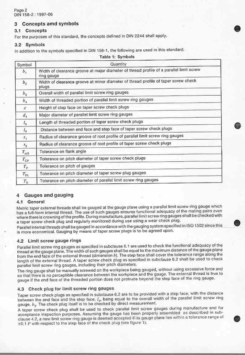
3 Concepts and symbols
3.1 Concepts
For the purposes of this standard, the concepts defined in DIN 2244 shall apply.
3.2 Symbols
In addition to the symbols specified in DIN 158-1, the following are used in this standard.
| Symbol | Quantity |
|---|---|
| b1 | Width of clearance groove at major diameter of thread profile of a parallel limit screw ring gauge |
| b2 | Width of clearance groove at minor diameter of thread profile of taper screw check plugs |
| b3 | Overall width of parallel limit screw ring gauges |
| b4 | Width of threaded portion of parallel limit screw ring gauges |
| c | Height of step face on taper screw check plugs |
| d4 | Major diameter of parallel limit screw ring gauges |
| l3 | Length of threaded portion of taper screw check plugs |
| l4 | Distance between end face and step face of taper screw check plugs |
| r1 | Radius of clearance groove of root profile of parallel limit screw ring gauges |
| r2 | Radius of clearance groove of root profile of taper screw check plugs |
| Tω/2 | Tolerance on flank angle |
| TCP | Tolerance on pitch diameter of taper screw check plugs |
| TP | Tolerance on pitch of gauges |
| TPL | Tolerance on pitch diameter of taper screw plug gauges |
| TR | Tolerance on pitch diameter of parallel limit screw ring gauges |
4 Gauges and gauging
4.1 General
Metric taper external threads shall be gauged at the gauge plane using a parallel limit screw ring gauge which has a full-form internal thread. The use of such gauges ensures functional adequacy of the mating pairs even where there is crowning of the profile. During manufacture, parallel limit screw ring gauges shall be checked with a taper screw check plug and regularly monitored during use using a wear check plug.
Parallel internal threads shall be gauged in accordance with the gauging system specified in ISO 1502 since this is more economical. Gauging by means of taper screw plugs is to be agreed upon.
4.2 Limit screw gauge rings
Parallel limit screw ring gauges as specified in subclause 6.1 are used to check the functional adequacy of the thread at the gauge plane. The width of such gauges shall be equal to the maximum distance of the gauge plane from the end face of the external thread (dimension b). The step face shall cover the tolerance range along the length of the external thread. A taper screw check plug as specified in subclause 6.2 shall be used to check parallel limit screw ring gauges, including their pitch diameters.
The ring gauge shall be manually screwed on the workpiece being gauged, without using excessive force and so that there is no perceptible clearance between the workpiece and the gauge. The external thread is true to gauge if the end face of the threaded portion does not protrude beyond the step face of the ring gauge.
4.3 Check plug for limit screw ring gauges
Taper screw check plugs as specified in subclause 6.2 are to be provided with a step face, with the distance between the end face and the step face, l4, being equal to the overall width of the parallel limit screw ring gauge, b3. The check plug itself is to be checked by direct measurement.
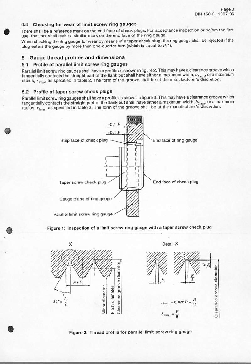
A taper screw check plug shall be used to check parallel limit screw gauges during manufacture and for acceptance inspection purposes. Assuming the gauge has been properly assembled as described in subclause 4.2, a new limit screw ring gauge is deemed accepted if its gauge plane lies within a tolerance range of ±0,1 P with respect to the step face of the check plug (see figure 1).
2
4.4 Checking for wear of limit screw ring gauges
There shall be a reference mark on the end face of check plugs. For acceptance inspection or before the first use, the user shall make a similar mark on the end face of the ring gauge.
When checking the ring gauge for wear by means of a taper check plug, the ring gauge shall be rejected if the plug enters the gauge by more than one-quarter turn (which is equal to P/4).
5 Gauge thread profiles and dimensions
5.1 Profile of parallel limit screw ring gauges
Parallel limit screw ring gauges shall have a profile as shown in figure 2. This may have a clearance groove which tangentially contacts the straight part of the flank but shall have either a maximum width, b1max, or a maximum radius, r1max, as specified in table 2. The form of the groove shall be at the manufacturer's discretion.
5.2 Profile of taper screw check plugs
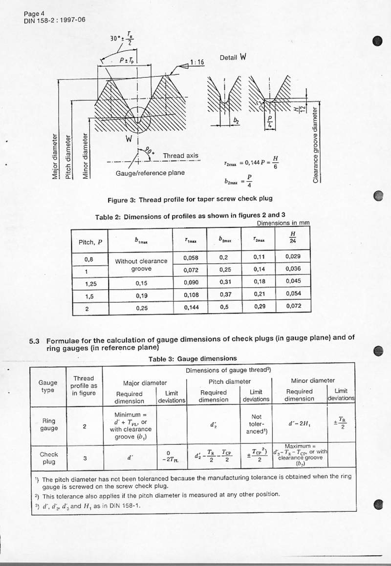
Parallel limit screw ring gauges shall have a profile as shown in figure 3. This may have a clearance groove which tangentially contacts the straight part of the flank but shall have either a maximum width, b2max, or a maximum radius, r2max, as specified in table 2. The form of the groove shall be at the manufacturer's discretion.
Figure 1: Inspection of a limit screw ring gauge with a taper screw check plug
Figure 2: Thread profile for parallel limit screw ring gauge
3
Figure 3: Thread profile for taper screw check plug
r2max = 0,144 P = H/6
b2max = P/4
| Pitch, P | b1max | r1max | b2max | r2max | H/24 |
|---|---|---|---|---|---|
| 0,8 | Without clearance groove | 0,058 | 0,2 | 0,11 | 0,029 |
| 1 | 0,072 | 0,25 | 0,14 | 0,036 | |
| 1,25 | 0,15 | 0,090 | 0,31 | 0,18 | 0,045 |
| 1,5 | 0,19 | 0,108 | 0,37 | 0,21 | 0,054 |
| 2 | 0,25 | 0,144 | 0,5 | 0,29 | 0,072 |
5.3 Formulae for the calculation of gauge dimensions of check plugs (in gauge plane) and of ring gauges (in reference plane)
| Gauge type | Thread profile as in figure | Major diameter | Pitch diameter | Minor diameter | |||
|---|---|---|---|---|---|---|---|
| Required dimension | Limit deviations | Required dimension | Limit deviations | Required dimension | Limit deviations | ||
| Ring gauge | 2 | Minimum = d' + TPL, or with clearance groove (b1) | d'2 | Not tolerated1) | d' − 2H1 | ±TR/2 | |
| Check plug | 3 | d' | 0 / −2TR | d'2 − TR/2 − TCP/2 | ±(TCP2))/2 | Maximum = d'3 − TR − TCP, or with clearance groove (b2) | |
1) The pitch diameter has not been tolerated because the manufacturing tolerance is obtained when the ring gauge is screwed on the screw check plug.
2) This tolerance also applies if the pitch diameter is measured at any other position.
3) d', d'2, d'3 and H1 as in DIN 158-1.
4
5.4 Manufacturing tolerances for gauges
| Thread size | Dimensions in μm | ||||
|---|---|---|---|---|---|
| Standard design | Short design | TR | TPL | TCP | TP1) |
| M 5 keg | M 6 keg M 8 × 1 keg to M 12 × 1 keg M 10 × 1,25 keg and M 12 × 1,25 keg |
10 | 8 | 8 | 5 |
| M 6 keg M 8 × 1 keg to M 12 × 1 keg M 10 × 1,25 keg and M 12 × 1,25 keg |
M 12 × 1,5 keg to M 30 × 1,5 keg | 14 | 10 | 8 | 5 |
| M 12 × 1,5 keg to M 52 × 1,5 keg M 27 × 2 keg to M 33 × 2 keg |
M 33 × 1,5 keg to M 52 × 1,5 keg M 27 × 2 keg to M 60 × 2 keg |
18 | 12 | 10 | 5 |
| M 36 × 2 keg to M 60 × 2 keg | – | 24 | 14 | 12 | 5 |
| 1) The pitch tolerance, TP, applies to any number of threads within the threaded portion of the gauge. The tolerance zone for the pitch may lie either above or below the zero line with respect to the basic size. | |||||
| Pitch, P, in mm | Tα/2 |
|---|---|
| 0,8 | ± 16 |
| 1 | ± 14 |
| 1,25 | ± 13 |
| 1,5 | ± 12 |
| 2 | ± 10 |
6 Designation and design features of gauges
6.1 Parallel limit screw ring gauge
Dimensions in mm
Limit screw ring gauge (Z)
1) Edges as in DIN 6784.
Figure 4: Limit screw ring gauge
5
Page 6
DIN 158-2 : 1997-06
Designation of a parallel limit screw ring gauge (Z) for metric taper external thread M 30 × 2 keg, standard design:
Ring gauge DIN 158 – Z – M 30 × 2 keg
Designation of a parallel limit screw ring gauge (Z) for metric taper external thread M 30 × 2 keg, short design:
Ring gauge DIN 158 – Z – M 30 × 2 keg short
| Thread size | Standard design | Short design | d4 | ||||||
|---|---|---|---|---|---|---|---|---|---|
| b3 | Limit deviations | b4 | Limit deviations | b3 | Limit deviations | b4 | Limit deviations | ||
| M 5 keg | 3,3 | ± 0,01 | 2,3 | ± 0,01 | – | – | – | – | 22 |
| M 6 keg | 4,2 | ± 0,014 | 2,8 | ± 0,014 | 3,5 | ± 0,01 | 2,5 | ± 0,01 | 32 |
| M 8 × 1 keg | 38 | ||||||||
| M 10 × 1 keg | 38 | ||||||||
| M 12 × 1 keg | 38 | ||||||||
| M 10 × 1,25 keg | 5,9 | ± 0,018 | 4,1 | ± 0,018 | 4,85 | ± 0,013 | 3,55 | ± 0,013 | 32 |
| M 12 × 1,25 keg | 38 | ||||||||
| M 12 × 1,5 keg | 7,5 | ± 0,02 | 5,5 | ± 0,02 | 6,25 | ± 0,015 | 4,75 | ± 0,015 | 38 |
| M 14 × 1,5 keg | 45 | ||||||||
| M 16 × 1,5 keg | 45 | ||||||||
| M 18 × 1,5 keg | 53 | ||||||||
| M 20 × 1,5 keg | 53 | ||||||||
| M 22 × 1,5 keg | 63 | ||||||||
| M 24 × 1,5 keg | 63 | ||||||||
| M 26 × 1,5 keg | 63 | ||||||||
| M 27 × 1,5 keg | 63 | ||||||||
| M 30 × 1,5 keg | 63 | ||||||||
| M 33 × 1,5 keg | 9,5 | ± 0,03 | 6,5 | ± 0,03 | 7,9 | ± 0,02 | 5,9 | ± 0,02 | 71 |
| M 36 × 1,5 keg | 71 | ||||||||
| M 38 × 1,5 keg | 85 | ||||||||
| M 39 × 1,5 keg | 85 | ||||||||
| M 42 × 1,5 keg | 100 | ||||||||
| M 45 × 1,5 keg | 100 | ||||||||
| M 48 × 1,5 keg | 100 | ||||||||
| M 52 × 1,5 keg | 100 | ||||||||
| M 27 × 2 keg | 10,5 | ± 0,03 | 7,5 | ± 0,03 | 9 | ± 0,02 | 7 | ± 0,02 | 63 |
| M 30 × 2 keg | 71 | ||||||||
| M 33 × 2 keg | 71 | ||||||||
| M 36 × 2 keg | 11,8 | ± 0,036 | 8,2 | ± 0,036 | 10 | ± 0,024 | 7,6 | ± 0,024 | 71 |
| M 39 × 2 keg | 85 | ||||||||
| M 42 × 2 keg | 85 | ||||||||
| M 45 × 2 keg | 100 | ||||||||
| M 48 × 2 keg | 100 | ||||||||
| M 52 × 2 keg | 100 | ||||||||
| M 56 × 2 keg | 100 | ||||||||
| M 60 × 2 keg | 100 | ||||||||
6
预览内容由文件识别整理,表格、公式及文字请以原始文件为准。
原文图片预览
PAGE IMAGES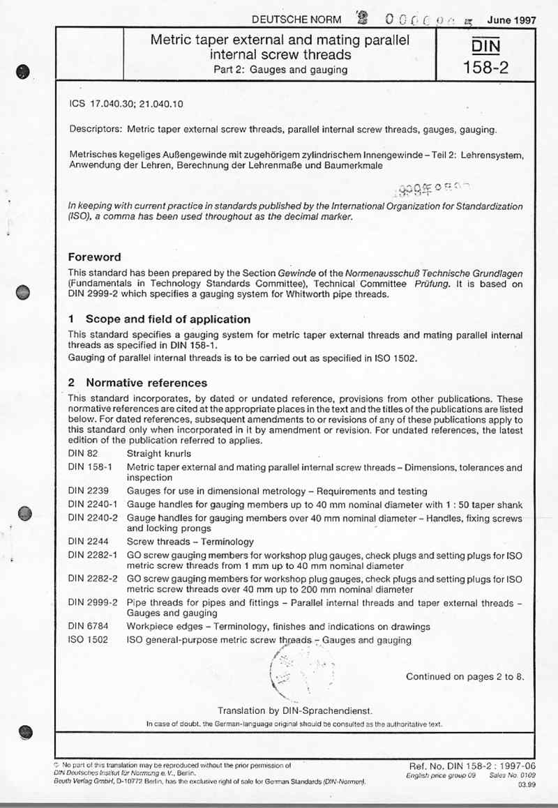
下载标准文件
DIN 158-2
英语 · PDF · 6 页 · 3.25 MB