din-76-2
符合ISO 228第1部分的管螺纹的螺纹收尾和螺纹退刀槽
din-76-2
Thread run-outs and thread undercuts for pipe threads conforming to ISO 228 Part 1
标准信息
STANDARD INFORMATION- 标准编号
- din-76-2
- 所属分类
- DIN 德国标准
- 发布机构
- DIN
- 版本年份
- 1983
- 文件语言
- 英语
- 文件格式
- 文件页数
- 6 页
- 文件大小
- 238.88 KB
中文名称为参考译名,文件语言以原文为准。
· 更新:
标准简介
OVERVIEW中文简介
该标准规定了符合ISO 228第1部分标准的平行管螺纹零件的螺纹收尾和螺纹退刀槽规格。它适用于所有引用此标准的标准零件,并建议用于非标准化零件。文档详细列出了外螺纹和内螺纹(盲孔)在不同尺寸下的具体尺寸参数、代号及测试要求。
English summary
This standard specifies thread run-outs and thread undercuts for components with parallel pipe threads conforming to ISO 228 Part 1. It applies to all standard parts referencing this standard and is recommended for non-standardized components. The document details specific dimensional parameters, designations, and testing requirements for external and internal (blind tapped) threads across various sizes.
以上为根据文件整理的内容简介。
相关标签
标准内容预览
DOCUMENT PREVIEWThread run-outs and thread undercuts for pipe threads conforming to ISO 228 Part 1
Gewindeausläufe, Gewindefreistiche für Rohrgewinde nach ISO 228 Teil 1
Supersedes November 1953 edition.
In keeping with current practice in standards published by the International Organization for Standardization (ISO), a comma has been used throughout as the decimal marker.
Dimensions in mm
1 Scope and field of application
This standard incorporates specifications for thread run-outs and thread undercuts for components with parallel pipe thread conforming to ISO 228 Part 1. It applies to all standard parts, providing reference is made to this standard. In case of necessity, the letter symbols given here may be used. It is recommended that this standard also be adopted for non-standardized components with pipe thread as specified in ISO 228 Part 1.
2 Dimensions, designation
2.1 External thread
2.1.1 Thread run-out
x1 normal
x2 short
2.1.2 Distance from the last full form thread to the bearing face
(for components threaded almost up to the head)
a1 normal
a2 short
a3 long
2.1.3 Thread undercut
Type A2 normal
Type B2 short
Designation of a type B2 thread undercut: Thread undercut DIN 76 – B2
*) Previously f and f2 respectively.
Continued on pages 2 and 3
1
Table 1.
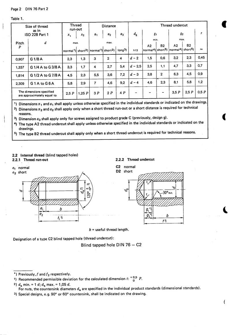
| Size of thread as in ISO 228 Part 1 | Thread run-out | Distance | Thread undercut | r | ||||||||
|---|---|---|---|---|---|---|---|---|---|---|---|---|
| Pitch P | d | x1 max. normal1) | x2 max. short2) | a1 max. normal1) | a2 max. short2) | a3 long3) | dg h13 | g1 min. A2 normal4) | g1 min. B2 short5) | g2 max. A2 normal4) | g2 max. B2 short5) | ≈ |
| 0,907 | G 1/8 A | 2,3 | 1,3 | 3 | 2 | 4 | d − 2 | 1,5 | 0,6 | 3,2 | 2,3 | 0,45 |
| 1,337 | G 1/4 A to G 3/8 A | 3,3 | 1,7 | 4 | 2,7 | 5,4 | d − 2,5 | 2,5 | 1,1 | 4,7 | 3,3 | 0,7 |
| 1,814 | G 1/2 A to G 7/8 A | 4,5 | 2,3 | 5,5 | 3,6 | 7,2 | d − 3 | 3,8 | 2 | 6,3 | 4,5 | 0,9 |
| 2,309 | G 1 A to G 6 A | 5,8 | 2,9 | 7 | 4,6 | 9,2 | d − 4 | 4,6 | 2,3 | 8,1 | 5,8 | 1,2 |
| The dimensions specified are approximately equal to | 2,5 P | 1,25 P | 3 P | 2 P | 4 P | – | – | – | 3,5 P | 2,5 P | 0,5 P | |
1) Dimensions x1 and a1 shall apply unless otherwise specified in the individual standards or indicated on the drawings.
2) Dimensions x2 and a2 shall apply only when a short thread run-out or a short distance is required for technical reasons.
3) Dimension a3 shall apply only for screws assigned to product grade C (previously, design g).
4) The type A2 thread undercut shall apply unless otherwise specified in the individual standards or indicated on the drawings.
5) The type B2 thread undercut shall apply only when a short thread undercut is required for technical reasons.
2.2 Internal thread (blind tapped holes)
2.2.1 Thread run-out
e1 normal
e2 short
2.2.2 Thread undercut
C2 normal
D2 short
b = useful thread length.
Designation of a type C2 blind tapped hole (thread undercut):
Blind tapped hole DIN 76 – C2
*) Previously, f and f2 respectively.
1) Recommended permissible deviation for the calculated dimension t: +0,50 P.
2) da min. = 1 d; da max. = 1,05 d.
For nuts, the countersink diameters da are specified in the individual product standards (dimensional standards).
3) Special designs, e.g. 90° or 60° countersink, shall be indicated on the drawing.
2
Table 2.
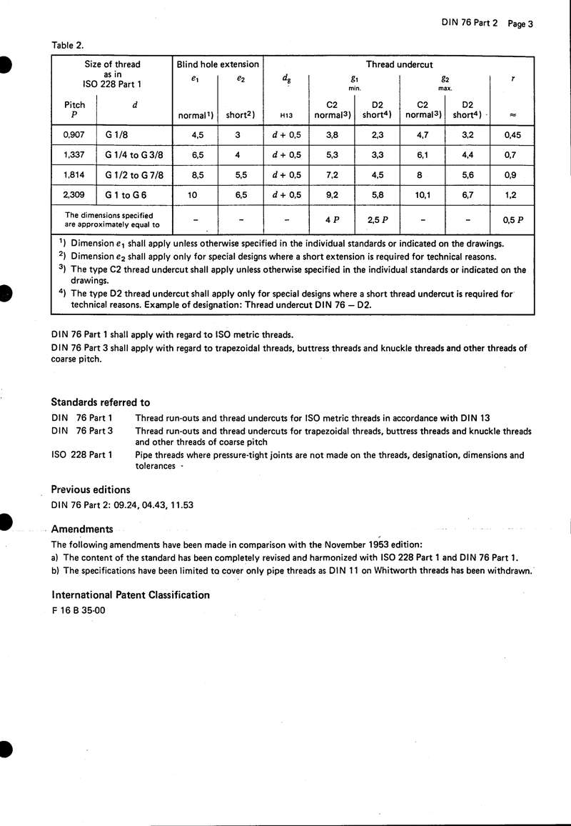
| Size of thread as in ISO 228 Part 1 | Blind hole extension | Thread undercut | r | ||||||
|---|---|---|---|---|---|---|---|---|---|
| Pitch P | d | e1 normal1) | e2 short2) | dg H13 | g1 min. C2 normal3) | D2 short4) | g2 max. C2 normal3) | D2 short4) | ≈ |
| 0,907 | G 1/8 | 4,5 | 3 | d + 0,5 | 3,8 | 2,3 | 4,7 | 3,2 | 0,45 |
| 1,337 | G 1/4 to G 3/8 | 6,5 | 4 | d + 0,5 | 5,3 | 3,3 | 6,1 | 4,4 | 0,7 |
| 1,814 | G 1/2 to G 7/8 | 8,5 | 5,5 | d + 0,5 | 7,2 | 4,5 | 8 | 5,6 | 0,9 |
| 2,309 | G 1 to G 6 | 10 | 6,5 | d + 0,5 | 9,2 | 5,8 | 10,1 | 6,7 | 1,2 |
| The dimensions specified are approximately equal to | - | - | - | 4 P | 2,5 P | - | - | 0,5 P | |
|
1) Dimension e1 shall apply unless otherwise specified in the individual standards or indicated on the drawings. 2) Dimension e2 shall apply only for special designs where a short extension is required for technical reasons. 3) The type C2 thread undercut shall apply unless otherwise specified in the individual standards or indicated on the drawings. 4) The type D2 thread undercut shall apply only for special designs where a short thread undercut is required for technical reasons. Example of designation: Thread undercut DIN 76 — D2. |
|||||||||
DIN 76 Part 1 shall apply with regard to ISO metric threads.
DIN 76 Part 3 shall apply with regard to trapezoidal threads, buttress threads and knuckle threads and other threads of coarse pitch.
Standards referred to
| DIN 76 Part 1 | Thread run-outs and thread undercuts for ISO metric threads in accordance with DIN 13 |
| DIN 76 Part 3 | Thread run-outs and thread undercuts for trapezoidal threads, buttress threads and knuckle threads and other threads of coarse pitch |
| ISO 228 Part 1 | Pipe threads where pressure-tight joints are not made on the threads, designation, dimensions and tolerances |
Previous editions
DIN 76 Part 2: 09.24, 04.43, 11.53
Amendments
The following amendments have been made in comparison with the November 1953 edition:
a) The content of the standard has been completely revised and harmonized with ISO 228 Part 1 and DIN 76 Part 1.
b) The specifications have been limited to cover only pipe threads as DIN 11 on Whitworth threads has been withdrawn.
International Patent Classification
F 16 B 35-00
3
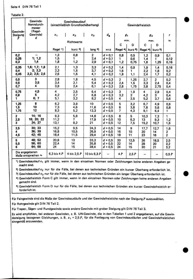
Seite 4 DIN 76 Teil 1
Tabelle 2.
| Gewinde-Steigung P | Gewinde-Nenndurchmesser (Regel-Gewinde) d | Gewindeauslauf (einschließlich Grundlochüberhang) | Gewindefreistich | |||||||
|---|---|---|---|---|---|---|---|---|---|---|
| Richtwerte | dg | g1 min. | g2 max. | r ≈ | ||||||
| e1 Regel 1) | e2 kurz 2) | e3 lang 3) | C Regel 4) | D kurz 5) | C Regel 4) | D kurz 5) | ||||
| 0,2 | — | 1,3 | 0,8 | 2 | d + 0,1 | 0,8 | 0,5 | 1,2 | 0,9 | 0,1 |
| 0,25 | 1; 1,2 | 1,5 | 1 | 2,4 | d + 0,1 | 1 | 0,6 | 1,4 | 1 | 0,12 |
| 0,3 | 1,4 | 1,8 | 1,2 | 2,9 | d + 0,1 | 1,2 | 0,75 | 1,6 | 1,25 | 0,16 |
| 0,35 | 1,6; 1,7; 1,8 | 2,1 | 1,3 | 3,3 | d + 0,2 | 1,4 | 0,9 | 1,9 | 1,4 | 0,16 |
| 0,4 | 2; 2,3 | 2,3 | 1,5 | 3,7 | d + 0,2 | 1,6 | 1 | 2,2 | 1,6 | 0,2 |
| 0,45 | 2,2; 2,5; 2,6 | 2,6 | 1,6 | 4,1 | d + 0,2 | 1,8 | 1,1 | 2,4 | 1,7 | 0,2 |
| 0,5 | 3 | 2,8 | 1,8 | 4,5 | d + 0,3 | 2 | 1,25 | 2,7 | 2 | 0,2 |
| 0,6 | 3,5 | 3,4 | 2,1 | 5,4 | d + 0,3 | 2,4 | 1,5 | 3,3 | 2,4 | 0,4 |
| 0,7 | 4 | 3,8 | 2,4 | 6,1 | d + 0,3 | 2,8 | 1,75 | 3,8 | 2,75 | 0,4 |
| 0,75 | 4,5 | 4 | 2,5 | 6,4 | d + 0,3 | 3 | 1,9 | 4 | 2,9 | 0,4 |
| 0,8 | 5 | 4,2 | 2,7 | 6,8 | d + 0,3 | 3,2 | 2 | 4,2 | 3 | 0,4 |
| 1 | 6; 7 | 5,1 | 3,2 | 8,2 | d + 0,5 | 4 | 2,5 | 5,2 | 3,7 | 0,6 |
| 1,25 | 8 | 6,2 | 3,9 | 10 | d + 0,5 | 5 | 3,2 | 6,7 | 4,9 | 0,6 |
| 1,5 | 10 | 7,3 | 4,6 | 11,6 | d + 0,5 | 6 | 3,8 | 7,8 | 5,6 | 0,8 |
| 1,75 | 12 | 8,3 | 5,2 | 13,3 | d + 0,5 | 7 | 4,3 | 9,1 | 6,4 | 1 |
| 2 | 14; 16 | 9,3 | 5,8 | 14,8 | d + 0,5 | 8 | 5 | 10,3 | 7,3 | 1 |
| 2,5 | 18; 20; 22 | 11,2 | 7 | 17,9 | d + 0,5 | 10 | 6,3 | 13 | 9,3 | 1,2 |
| 3 | 24; 27 | 13,1 | 8,2 | 21 | d + 0,5 | 12 | 7,5 | 15,2 | 10,7 | 1,6 |
| 3,5 | 30; 33 | 15,2 | 9,5 | 24,3 | d + 0,5 | 14 | 9 | 17,7 | 12,7 | 1,6 |
| 4 | 36; 39 | 16,8 | 10,5 | 26,9 | d + 0,5 | 16 | 10 | 20 | 14 | 2 |
| 4,5 | 42; 45 | 18,4 | 11,5 | 29,4 | d + 0,5 | 18 | 11 | 23 | 16 | 2 |
| 5 | 48; 52 | 20,8 | 13 | 33,3 | d + 0,5 | 20 | 12,5 | 26 | 18,5 | 2,5 |
| 5,5 | 56; 60 | 22,4 | 14 | 35,8 | d + 0,5 | 22 | 14 | 28 | 20 | 3,2 |
| 6 | 64; 68 | 24 | 15 | 38,4 | d + 0,5 | 24 | 15 | 30 | 21 | 3,2 |
| Die angegebenen Maße entsprechen ≈ | 6,3 bis 4 P | 4 bis 2,5 P | 10 bis 6,3 P | — | 4 P | 2,5 P | — | — | 0,5 P | |
| 1) Gewindeauslauf e1 gilt immer, wenn in den einzelnen Normen oder Zeichnungen keine anderen Angaben gemacht sind. | ||||||||||
| 2) Gewindeauslauf e2 nur für die Fälle, bei denen aus technischen Gründen ein kurzer Überhang erforderlich ist. | ||||||||||
| 3) Gewindeauslauf e3 nur für die Fälle, bei denen aus technischen Gründen ein langer Überhang erforderlich ist. | ||||||||||
| 4) Gewindefreistich Form C gilt immer, wenn in den einzelnen Normen oder Zeichnungen keine anderen Angaben gemacht sind. | ||||||||||
| 5) Gewindefreistich Form D nur für die Fälle, bei denen aus technischen Gründen ein kurzer Gewindefreistich erforderlich ist. | ||||||||||
Für Feingewinde sind die Maße der Gewindeausläufe und der Gewindefreistiche nach der Steigung P auszuwählen.
Für Rohrgewinde gilt DIN 76 Teil 2.
Für Trapez-, Sägen- und Rundgewinde sowie andere Gewinde mit grober Steigung gilt DIN 76 Teil 3.
Es wird empfohlen, bei anderen Gewinden, z. B. UN-Gewinde, die in den Tabellen 1 und 2 angegebenen, auf die Gewindesteigung bezogenen Gleichungen, z. B. x1 = 2,5 P, für die Festlegung von Gewindeausläufen und Gewindefreistichen sinngemäß anzuwenden.
4
Zitierte Normen
| DIN 13 Teil 1 | Metrisches ISO-Gewinde; Regelgewinde von 1 bis 68 mm Gewindedurchmesser; Nennmaße |
| DIN 13 Teil 12 | Metrisches ISO-Gewinde; Regel- und Feingewinde von 1 bis 300 mm Durchmesser; Auswahl für Durchmesser und Steigungen |
| DIN 76 Teil 2 | Gewindeauslauf, Gewinderillen, Gewindeenden; Whitworth-Gewinde, Whitworth-Rohrgewinde |
| DIN 76 Teil 3 | Gewindeausläufe, Gewindefreistiche für Trapez-, Sägen- und Rundgewinde und andere Gewinde mit grober Steigung |
| ISO 4755 – 1983 | Fasteners – Thread undercuts for external metric ISO threads Verbindungselemente – Gewindefreistiche für metrisches ISO-Außengewinde |
Frühere Ausgaben
DIN 2352: 11.24; DIN LON 369 Teil 1 = DIN 30 140 Teil 1: 12.36; DIN 76 Teil 1: 09.24, 04.43, 11.53, 09.65, 06.67, 09.75
Änderungen
Gegenüber der Ausgabe September 1975, wurden folgende Änderungen vorgenommen:
a) Der Inhalt der Norm wurde mit den Internationalen Normen ISO 3508 – 1976 und ISO 4755 – 1983 abgestimmt.
b) Siehe Erläuterungen
Erläuterungen
Bei der letzten Überarbeitung von DIN 76 Teil 1 im Jahre 1975 war die Norm bereits bezüglich der Gewindeausläufe mit der damals in Vorbereitung befindlichen Internationalen Norm ISO 3508 abgestimmt worden. Diese Norm ist im Jahre 1976 erschienen und war praktisch identisch mit den Abschnitten 1.1 und 1.2 der Ausgabe September 1975 von DIN 76 Teil 1.
Inzwischen wurde ergänzend zu ISO 3508 die Norm ISO 4755 – 1983 erstellt. Diese enthält Gewindefreistiche für Außengewinde und führte zu einer Überprüfung von DIN 76 Teil 1.
Die vorliegende Folgeausgabe von DIN 76 Teil 1 berücksichtigt beide Normen und weicht nur beim Gewindefreistich Form A (Regelfall) für Außengewinde von ISO 4755 ab (g2 = 3,5 P statt 3 P). Ferner enthält die Norm weiterhin den bisherigen Gewindefreistich Form B (kurz) für Außengewinde, der in ISO 4755 nicht festgelegt ist. Bei den internationalen Normungsarbeiten war versucht worden, die Freistiche Form A (Regelfall) mit g2 = 3,5 P und Form B (Kurzfal) mit g2 = 2,5 P zu einem Freistich mit g2 = 3 P zu vereinigen. Nationale Prüfungen haben jedoch klar gezeigt, daß mit üblichen Werkzeugen ein g2 = 3 P nicht eingehalten werden kann, sondern 3,5 P erforderlich sind, wenn das Gewinde ganz bis in den Freistich hinein auslaufen soll und sichergestellt ist, daß bis zum Anschlag (Schraubenkopf) aufgeschraubt werden kann. Deshalb wurden die bisherigen zwei Arten von Gewindefreistichen (g2 = 3,5 P und g2 = 2,5 P) beibehalten, wobei g2 = 2,5 P nur für konstruktiv bedingte Ausnahmefälle gilt und dann Sonderwerkzeuge erforderlich sind. Es besteht die Absicht, einen entsprechenden Revisionsantrag zu ISO 4755 einzureichen.
Für den Gewindeauslauf bei Schrauben mit Schaftdurchmesser ≈ Flankendurchmesser wurde abweichend von den bisherigen Angaben nur noch der Gewindeauslauf x1 genannt. Er gilt als Größtmaß, wobei aufgrund des dünneren Schaftes angenommen werden darf, daß er im allgemeinen etwa 0,5 x1 betragen wird.
Internationale Patentklassifikation
F 16 B 35-00
5
6 Testing
If bricks are packaged, it shall be deemed sufficient if the packaging or an attached label gives the works mark, brick type, apparent brick density class and compressive strength class (for lightweight horizontally perforated bricks).
6.1 Shape, dimensions, perforation
In accordance with DIN 105 Part 1.
A measuring rule or a gauge board with a millimetre scale is sufficient for measuring the length of lightweight horizontally perforated brick panels with dimensions exceeding 495 mm.
The deflection shall also be determined for lightweight horizontally perforated brick panels as illustrated in figure 5. In this determination, the panel shall be pressed on a longitudinal face or width against a smooth surface. Deviations from straightness shall be determined using a measuring wedge and stated to the nearest whole millimetre.
6.2 Apparent brick density
In accordance with DIN 105 Part 1.
6.3 Compressive strength
In accordance with DIN 105 Part 1.
Lightweight horizontally perforated bricks, including standard format bricks, shall be tested as whole bricks. Form factors shall not be applied.
6.4 Bending strength
The bending strength of lightweight horizontally perforated brick panels shall be determined on 5 air-dried samples.
Each panel shall be tested lying flat. The panel shall be placed on two supports so that it can move and stressed in the middle parallel to the supports by means of a 20 mm wide mandrel. The distance between supports shall equal the length of the panel minus 50 mm. The load shall be increased steadily at a rate of approximately 10 N per second.
6.5 Expansive particles and water-soluble salts
In accordance with DIN 105 Part 1.
7 Inspection
7.1 General
See DIN 105 Part 1.
7.2 Internal control
In accordance with DIN 105 Part 1.
7.3 Third party inspection
In accordance with DIN 105 Part 1.
The inspection of lightweight horizontally perforated brick panels shall include the bending strength test instead of the compressive strength test and the determination of deflection.
8 Delivery note
In accordance with DIN 105 Part 1.
Standards referred to
DIN 105 Part 1 Clay bricks; solid bricks and vertically perforated bricks
International Patent Classification
E 04 C 1-00
6
预览内容由文件识别整理,表格、公式及文字请以原始文件为准。
原文图片预览
PAGE IMAGES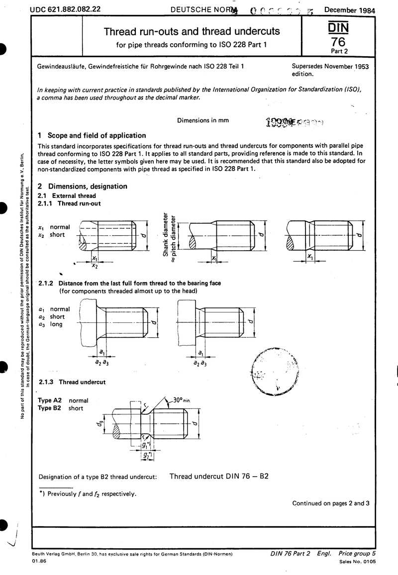
下载标准文件
din-76-2
英语 · PDF · 6 页 · 238.88 KB