DIN 267-30(1)
紧固件技术交货条件 第30部分:10.9级公制滚丝螺钉
DIN 267-30(1)
Technical delivery conditions for fasteners Part 30: Metric thread rolling screws of property class 10.9
标准信息
STANDARD INFORMATION- 标准编号
- DIN 267-30(1)
- 所属分类
- DIN 德国标准
- 发布机构
- DIN
- 版本年份
- 2000
- 文件语言
- 英语
- 文件格式
- 文件页数
- 6 页
- 文件大小
- 11.57 MB
中文名称为参考译名,文件语言以原文为准。
· 更新:
标准简介
OVERVIEW中文简介
该标准规定了10.9级公制滚丝螺钉的技术要求,适用于在最大维氏硬度130 HV或布氏硬度124 HB的材料中形成公称直径2mm至10mm的内螺纹。标准详细列出了螺钉的材料、热处理、机械性能(如最小断裂扭矩和拉伸载荷)以及测试方法。
English summary
This standard specifies the technical delivery conditions for metric thread rolling screws of property class 10.9. It covers requirements for screws designed to form internal threads with nominal diameters from 2 mm to 10 mm in materials with specific hardness limits. The document details material specifications, heat treatment, mechanical performance requirements, and testing methods.
以上为根据文件整理的内容简介。
相关标签
标准内容预览
DOCUMENT PREVIEWTechnical delivery conditions for fasteners
Part 30: Metric thread rolling screws of property class 10.9
ICS 21.060.10
Mechanische Verbindungselemente – Technische Lieferbedingungen – Teil 30: Metrische gewindefurchende Schrauben der Festigkeitsklasse 10.9
In keeping with current practice in standards published by the International Organization for Standardization (ISO), a comma has been used throughout as the decimal marker.
Foreword
This standard has been prepared by Technical Committee Kleinschrauben of the Normenausschuss Mechanische Verbindungselemente (Fasteners Standards Committee). It includes additional specifications for case hardened and tempered metric thread rolling screws as in DIN EN ISO 7085.
All dimensions are in millimetres.
1 Scope
This standard specifies requirements for metric thread rolling screws of property class 10.9 designed to produce internal threads with nominal diameters from 2 mm to 10 mm in materials with a maximum Vickers hardness of 130 HV or a maximum Brinell hardness of 124 HB, which fit general purpose ISO metric screw threads for use in general applications.
2 Normative references
This standard incorporates, by dated or undated reference, provisions from other publications. These normative references are cited at the appropriate places in the text, and the titles of the publications are listed below. For dated references, subsequent amendments to or revisions of any of these publications apply to this standard only when incorporated in it by amendment or revision. For undated references, the latest edition of the publication referred to applies.
| DIN 4000-2 | Tabular layouts of article characteristics for bolts, screws and fit bolts |
| DIN EN 20898-7 | Mechanical properties of fasteners – Part 7: Torsional test and minimum torques for bolts and screws with nominal diameters 1 mm to 10 mm (ISO 898-7 : 1992) |
| DIN EN ISO 898-1 | Mechanical properties of fasteners made of carbon steel and alloy steel – Part 1: Bolts, screws and studs (ISO 898-1 : 1999) |
| DIN EN ISO 4042 | Fasteners – Electroplated coatings (ISO 4042 : 1999) |
| DIN EN ISO 10683 | Fasteners – Non-electrically applied zinc flake coatings (ISO/DIS 10683 : 1999)* |
| DIN EN ISO 15330 | Fasteners – Preloading test for the detection of hydrogen embrittlement – Parallel bearing surface method (ISO 15330 : 1999) |
| DIN ISO 261 | ISO general purpose metric screw threads – General plan (ISO 261 : 1998) |
*) Currently at draft stage.
Continued on pages 2 and 3.
Translation by DIN-Sprachendienst.
In case of doubt, the German-language original should be consulted as the authoritative text.
1
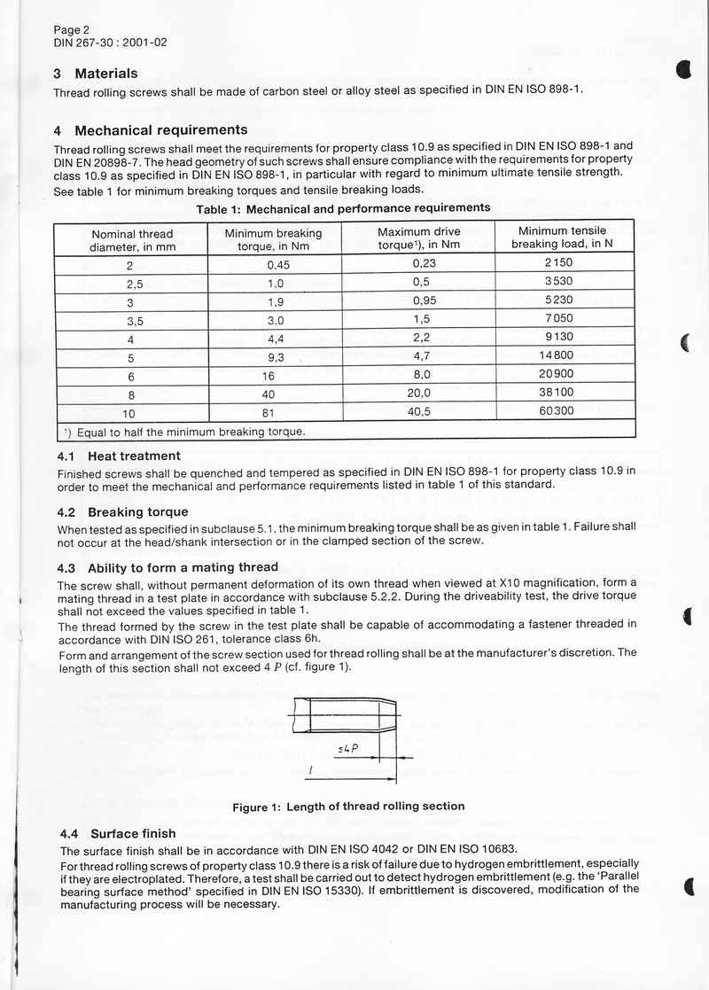
3 Materials
Thread rolling screws shall be made of carbon steel or alloy steel as specified in DIN EN ISO 898-1.
4 Mechanical requirements
Thread rolling screws shall meet the requirements for property class 10.9 as specified in DIN EN ISO 898-1 and DIN EN 20898-7. The head geometry of such screws shall ensure compliance with the requirements for property class 10.9 as specified in DIN EN ISO 898-1, in particular with regard to minimum ultimate tensile strength. See table 1 for minimum breaking torques and tensile breaking loads.
| Nominal thread diameter, in mm | Minimum breaking torque, in Nm | Maximum drive torque1), in Nm | Minimum tensile breaking load, in N |
|---|---|---|---|
| 2 | 0,45 | 0,23 | 2 150 |
| 2,5 | 1,0 | 0,5 | 3 530 |
| 3 | 1,9 | 0,95 | 5 230 |
| 3,5 | 3,0 | 1,5 | 7 050 |
| 4 | 4,4 | 2,2 | 9 130 |
| 5 | 9,3 | 4,7 | 14 800 |
| 6 | 16 | 8,0 | 20 900 |
| 8 | 40 | 20,0 | 38 100 |
| 10 | 81 | 40,5 | 60 300 |
| 1) Equal to half the minimum breaking torque. | |||
4.1 Heat treatment
Finished screws shall be quenched and tempered as specified in DIN EN ISO 898-1 for property class 10.9 in order to meet the mechanical and performance requirements listed in table 1 of this standard.
4.2 Breaking torque
When tested as specified in subclause 5.1, the minimum breaking torque shall be as given in table 1. Failure shall not occur at the head/shank intersection or in the clamped section of the screw.
4.3 Ability to form a mating thread
The screw shall, without permanent deformation of its own thread when viewed at X10 magnification, form a mating thread in a test plate in accordance with subclause 5.2.2. During the driveability test, the drive torque shall not exceed the values specified in table 1.
The thread formed by the screw in the test plate shall be capable of accommodating a fastener threaded in accordance with DIN ISO 261, tolerance class 6h.
Form and arrangement of the screw section used for thread rolling shall be at the manufacturer's discretion. The length of this section shall not exceed 4 P (cf. figure 1).
Figure 1: Length of thread rolling section
4.4 Surface finish
The surface finish shall be in accordance with DIN EN ISO 4042 or DIN EN ISO 10683.
For thread rolling screws of property class 10.9 there is a risk of failure due to hydrogen embrittlement, especially if they are electroplated. Therefore, a test shall be carried out to detect hydrogen embrittlement (e.g. the 'Parallel bearing surface method' specified in DIN EN ISO 15330). If embrittlement is discovered, modification of the manufacturing process will be necessary.
2
5 Testing
Thread rolling screws shall be tested using the methods specified in DIN EN ISO 898-1.
5.1 Torsional test
The screw to be tested shall be securely clamped in a suitable device (cf. DIN EN 20898-7), with at least two full threads projecting above the device and at least two full threads held in the clamping device.
Using a suitable calibrated torque-measuring device, torque shall be applied to the screw until failure occurs. The torque required to cause failure shall be recorded as the breaking torque.
5.2 Driveability test
5.2.1 Determining the thread rolling capability
The screw to be tested shall be driven into a test plate (cf. subclause 5.2.2) until at least one full thread projects above the surface of the plate.
The thread rolling process shall be started by applying an axial force of 50 N for nominal thread diameters up to 5 mm and 100 N for nominal thread diameters over 5 mm. In arbitration cases, the driving speed shall not exceed 30 min-1 (30 r.p.m). The maximum torque measured during the test shall be regarded as the drive torque. Where necessary, a lubricant may be used to achieve the required drive torque.
5.2.2 Test plate
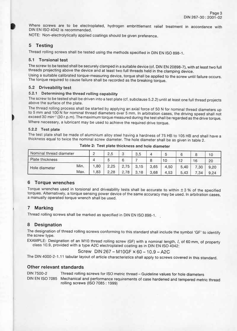
The test plate shall be made of aluminium alloy steel having a hardness of 75 HB to 105 HB and shall have a thickness equal to twice the nominal screw diameter. The hole diameter shall be as given in table 2.
| Nominal thread diameter | 2 | 2,5 | 3 | 3,5 | 4 | 5 | 6 | 8 | 10 |
|---|---|---|---|---|---|---|---|---|---|
| Plate thickness | 4 | 5 | 6 | 7 | 8 | 10 | 12 | 16 | 20 |
| Hole diameter Min. | 1,80 | 2,25 | 2,75 | 3,15 | 3,65 | 4,50 | 5,40 | 7,30 | 9,20 |
| Hole diameter Max. | 1,83 | 2,28 | 2,78 | 3,18 | 3,68 | 4,53 | 5,43 | 7,34 | 9,24 |
6 Torque wrenches
Torque wrenches used in torsional and driveability tests shall be accurate to within ± 3 % of the specified torques. Alternatively, a torque sensing power device of the same accuracy may be used. In arbitration cases, a manually operated torque wrench shall be used.
7 Marking
Thread rolling screws shall be marked as specified in DIN EN ISO 898-1.
8 Designation
The designation of thread rolling screws conforming to this standard shall include the symbol 'GF' to identify the screw type.
EXAMPLE: Designation of an M10 thread rolling screw (GF) with a nominal length, l, of 60 mm, of property class 10.9, provided with a type A2C electroplated coating as in DIN EN ISO 4042:
Screw DIN 267 – M10GF × 60 – 10.9 – A2C
The DIN 4000-2-1.11 tabular layout of article characteristics shall apply to screws covered in this standard.
Other relevant standards
DIN 7500-2 Thread rolling screws for ISO metric thread – Guideline values for hole diameters
DIN EN ISO 7085 Mechanical and performance requirements of case hardened and tempered metric thread rolling screws (ISO 7085 : 1999)
3
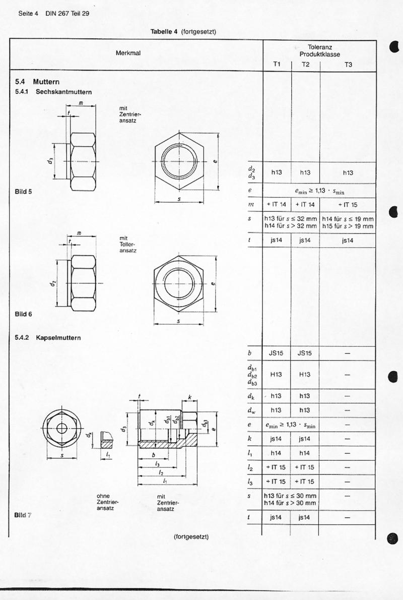
Tabelle 4 (fortgesetzt)
| Merkmal | Toleranz Produktklasse | ||
|---|---|---|---|
| T1 | T2 | T3 | |
|
5.4 Muttern 5.4.1 Sechskantmuttern Bild 5 Bild 6 5.4.2 Kapselmuttern Bild 7 |
|||
| d2 d3 |
h13 | h13 | h13 |
| e | emin ≥ 1,13 · smin | ||
| m | + IT 14 | + IT 14 | + IT 15 |
| s | h13 für s ≤ 32 mm h14 für s > 32 mm |
h14 für s ≤ 19 mm h15 für s > 19 mm |
|
| t | js14 | js14 | js14 |
| b | JS15 | JS15 | — |
| db1 db2 db3 |
H13 | H13 | — |
| dk | h13 | h13 | — |
| dw | h13 | h13 | — |
| e | emin ≥ 1,13 · smin | — | |
| k | js14 | js14 | — |
| l1 | h14 | h14 | — |
| l2 | + IT 15 | + IT 15 | — |
| l3 | + IT 15 | + IT 15 | — |
| s | h13 für s ≤ 30 mm h14 für s > 30 mm |
— | |
| t | js14 | js14 | — |
(fortgesetzt)
4
6 Toleranzen für Form und Lage
Tabelle 4 (abgeschlossen)
| Merkmal | Toleranz Produktklasse |
||
|---|---|---|---|
| T1 | T2 | T3 | |
| 5.5 Dehnhülsen Bild 8 |
|||
| d1 | — | h13 | — |
| d2 | — | H14 | — |
| l | — | h14 | — |
Die Toleranzen für Form und Lage sind unabhängig vom Herstell-, Meß- oder Prüfverfahren.
Ist als Bezugselement der Gewinde-Außendurchmesser d (Gewinde-Nenndurchmesser) eingetragen, so wird in der Gewindeflanke aufgenommen oder gemessen.
Tabelle 5: Toleranzen für Form und Lage
| Merkmal | Toleranz t Produktklasse |
||
|---|---|---|---|
| T1 | T2 | T3 | |
| 6.1 Koaxialität, Symmetrie und Rundlauf Bild 9 |
2 IT 10 | 2 IT 13 | — |
| Bild 10 | 2 IT 13 | 2 IT 14 | — |
| Bild 11 Bild 12 |
2 IT 12 | 2 IT 13 | 2 IT 14 (nur für Bild 11) |
| Bild 13 mit Telleransatz |
2 IT 12 | 2 IT 13 | 2 IT 14 |
(fortgesetzt)
5
6.2 Rechtwinkligkeitstoleranz
| Merkmal | Toleranz t Produktklasse | ||||||||||||
|---|---|---|---|---|---|---|---|---|---|---|---|---|---|
| T1 | T2 | T3 | |||||||||||
| Bild 14 | 2 IT 12 | 2 IT 12 | 2 IT 12 | ||||||||||
| Bild 15 | — | 2 IT 11 | — | ||||||||||
| Bild 16 | — |
|
— | ||||||||||
| Bild 17 | t = 0,0175 · Dm | — | |||||||||||
| Bild 18 | t = 0,009 · Dm | t = 0,0175 · Dm | — | ||||||||||
1) Siehe Seite 7
(fortgesetzt)
6
预览内容由文件识别整理,表格、公式及文字请以原始文件为准。
原文图片预览
PAGE IMAGES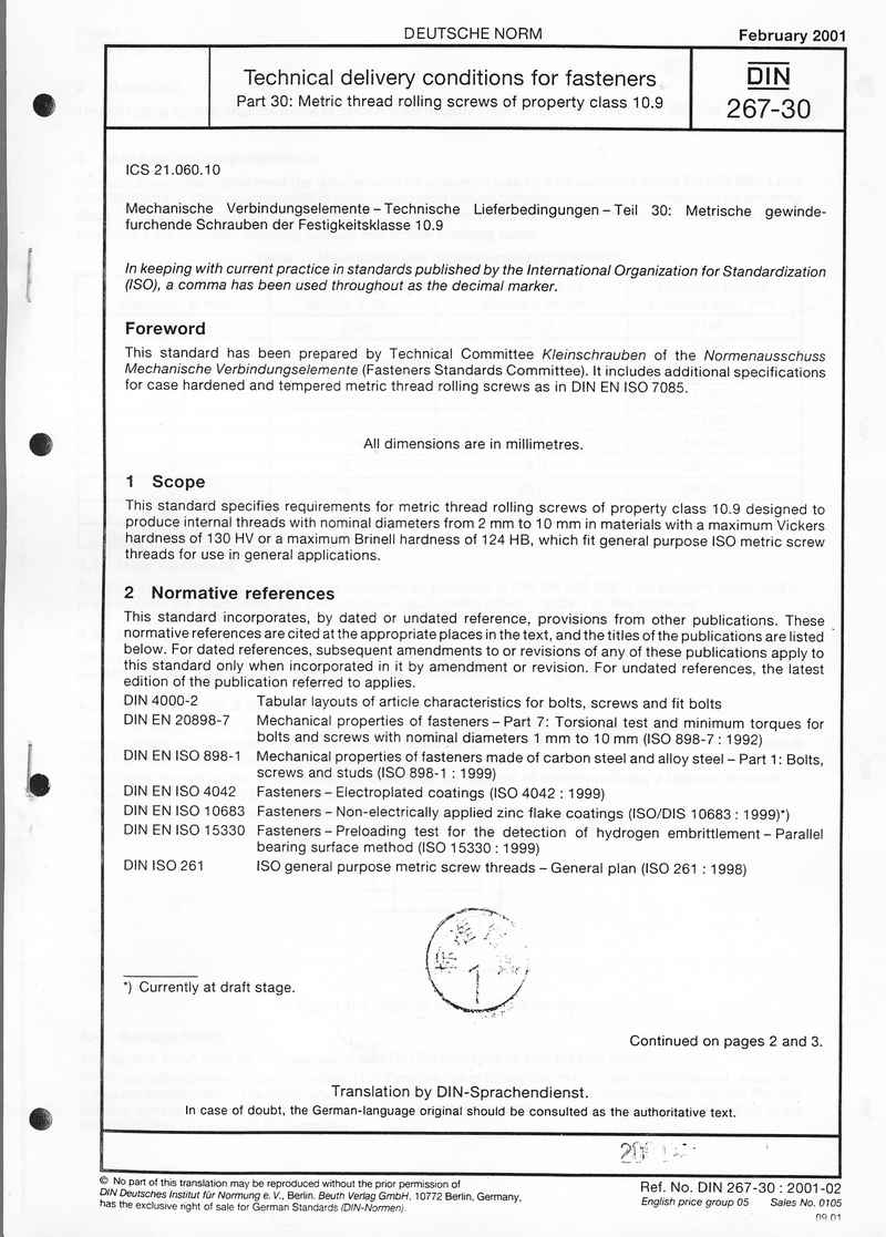
下载标准文件
DIN 267-30(1)
英语 · PDF · 6 页 · 11.57 MB