标准信息
STANDARD INFORMATION- 标准编号
- DIN 168-1(1)
- 所属分类
- DIN 德国标准
- 发布机构
- DIN
- 版本年份
- 1997
- 文件语言
- 英语
- 文件格式
- 文件页数
- 6 页
- 文件大小
- 7.96 MB
中文名称为参考译名,文件语言以原文为准。
· 更新:
标准简介
OVERVIEW中文简介
该标准规定了主要用于玻璃容器颈部封口的凸缘螺纹的尺寸。它涵盖了从GL 8到GL 125的各种螺纹规格,包括螺距、外径、内径及公差等详细参数。
English summary
This standard specifies the dimensions for knuckle threads intended mainly for glass container neck finishes. It covers thread sizes from GL 8 to GL 125, including details on pitch, major and minor diameters, and limit deviations.
以上为根据文件整理的内容简介。
相关标签
标准内容预览
DOCUMENT PREVIEWGlass container knuckle thread finishes
Thread sizes
ICS 21.040.30
Supersedes
December 1979 edition.
Descriptors: Knuckle thread, thread sizes, glass containers.
Rundgewinde – Teil 1: für Glasbehältnisse – Gewindemaße
In keeping with current practice in standards published by the International Organization for Standardization (ISO), a comma has been used throughout as the decimal marker.
Foreword
This standard has been prepared by the Normenausschuß Verpackungswesen (Packaging Standards Committee), Technical Committee Verpackungen aus Glas.
Amendments
In comparison with the December 1979 edition, the scope of the standard has been extended to include thread sizes GL 50 to GL 125, and the standard has been editorially revised.
Previous editions
DIN 168-1: 1951-03, 1971-07, 1979-12.
Dimensions in mm
1 Scope and field of application
This standard specifies dimensions for knuckle threads intended mainly for glass container neck finishes.
Continued on page 2.
Translation by DIN-Sprachendienst.
In case of doubt, the German-language original should be consulted as the authoritative text.
1
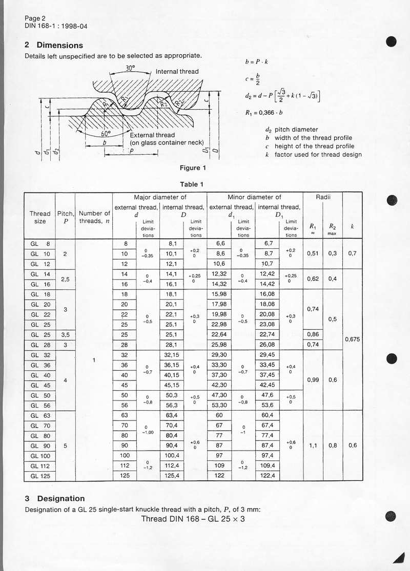
2 Dimensions
Details left unspecified are to be selected as appropriate.
b = P · k
c = b/2
d2 = d − P [√3/2 + k (1 − √3)]
R1 = 0,366 · b
Figure 1
d2 pitch diameter
b width of the thread profile
c height of the thread profile
k factor used for thread design
| Thread size | Pitch, P | Number of threads, n | Major diameter of external thread, d | internal thread, D | Minor diameter of external thread, d1 | internal thread, D1 | Radii | k | |||||
|---|---|---|---|---|---|---|---|---|---|---|---|---|---|
| Limit deviations | Limit deviations | Limit deviations | Limit deviations | R1 ≈ | R2 max | ||||||||
| GL 8 | 2 | 1 | 8 | 0 −0,35 | 8,1 | +0,2 0 | 6,6 | 0 −0,35 | 6,7 | +0,2 0 | 0,51 | 0,3 | 0,7 |
| GL 10 | 10 | 10,1 | 8,6 | 8,7 | |||||||||
| GL 12 | 12 | 12,1 | 10,6 | 10,7 | |||||||||
| GL 14 | 2,5 | 14 | 0 −0,4 | 14,1 | +0,25 0 | 12,32 | 0 −0,4 | 12,42 | +0,25 0 | 0,62 | 0,4 | 0,675 | |
| GL 16 | 16 | 16,1 | 14,32 | 14,42 | |||||||||
| GL 18 | 3 | 18 | 0 −0,5 | 18,1 | +0,3 0 | 15,98 | 0 −0,5 | 16,08 | +0,3 0 | 0,74 | 0,5 | ||
| GL 20 | 20 | 20,1 | 17,98 | 18,08 | |||||||||
| GL 22 | 22 | 22,1 | 19,98 | 20,08 | |||||||||
| GL 25 | 25 | 25,1 | 22,98 | 23,08 | 0,86 | ||||||||
| GL 25 | 3,5 | 25 | 25,1 | 22,64 | 22,74 | 0,74 | |||||||
| GL 28 | 3 | 28 | 28,1 | 25,98 | 26,08 | ||||||||
| GL 32 | 4 | 32 | 0 −0,7 | 32,15 | +0,4 0 | 29,30 | 0 −0,7 | 29,45 | +0,4 0 | 0,99 | 0,6 | ||
| GL 36 | 36 | 36,15 | 33,30 | 33,45 | |||||||||
| GL 40 | 40 | 40,15 | 37,30 | 37,45 | |||||||||
| GL 45 | 45 | 45,15 | 42,30 | 42,45 | |||||||||
| GL 50 | 50 | 0 −0,8 | 50,3 | +0,5 0 | 47,30 | 0 −0,8 | 47,6 | +0,5 0 | |||||
| GL 56 | 56 | 56,3 | 53,30 | 53,6 | |||||||||
| GL 63 | 5 | 63 | 0 −1,00 | 63,4 | +0,6 0 | 60 | 0 −1 | 60,4 | +0,6 0 | 1,1 | 0,8 | 0,6 | |
| GL 70 | 70 | 70,4 | 67 | 67,4 | |||||||||
| GL 80 | 80 | 80,4 | 77 | 77,4 | |||||||||
| GL 90 | 90 | 90,4 | 87 | 87,4 | |||||||||
| GL 100 | 100 | 100,4 | 97 | 97,4 | |||||||||
| GL 112 | 112 | 112,4 | 109 | 109,4 | |||||||||
| GL 125 | 125 | 125,4 | 122 | 122,4 | |||||||||
3 Designation
Designation of a GL 25 single-start knuckle thread with a pitch, P, of 3 mm:
Thread DIN 168 – GL 25 × 3
2
Form C
Senkrechte Anordnung mit Einlegeringen nach DIN 115 Blatt 2
Form CS
wie Form C, jedoch mit Stahlblechmantel
Eckenradius der Ringnute genau wie bei der Wellennute nach DIN 115 Blatt 2 ausgeführt
Bezeichnung einer Schalenkupplung Form C mit Bohrung d1 = 55 mm aus GG-20
Kupplung C 55 DIN 115 — GG-20
Tabelle 2.
| Schalenkupplung | Drehmoment T Form C (N m 2)) | Drehzahl n max. Form C CS (1/min) | Einlegering nach DIN 115 Blatt 2 für Form C und CS | Paßfeder nach DIN 6885 Blatt 1 für Form C und CS | ||||||||
|---|---|---|---|---|---|---|---|---|---|---|---|---|
| Bohrung d1 | Toleranzfeld 1) | d3 max. | d5 D9 | b D9 | l | s | w | Traglast N | ||||
| 25 | V7 | 110 | 35 | 8 | 160 | 4 | 28 | 40 | 1420 | 20 x 35 | 12000 | 8 x 7 x 56 |
| 30 | V7 | 110 | 40 | 8 | 160 | 4 | 28 | 60 | 1420 | 25 x 40 | 17000 | 8 x 7 x 56 |
| 35 | V7 | 120 | 45 | 8 | 190 | 4 | 28 | 80 | 1350 | 28 x 45 | 23000 | 10 x 8 x 70 |
| 40 | V7 | 130 | 50 | 8 | 190 | 4 | 28 | 100 | 1300 | 32 x 50 | 30000 | 12 x 8 x 70 |
| 45 | V7 | 150 | 56 | 10 | 220 | 4 | 32 | 125 | 1200 | 36 x 56 | 36000 | 14 x 9 x 80 |
| 50 | V7 | 150 | 62 | 10 | 220 | 4 | 32 | 150 | 1200 | 40 x 62 | 45000 | 14 x 9 x 80 |
| 55 | U7 | 170 | 70 | 12 | 250 | 4 | 36 | 500 | 1120 | 45 x 70 | 53000 | 16 x 10 x 90 |
| 60 | U7 | 170 | 75 | 12 | 250 | 4 | 36 | 850 | 1120 | 48 x 75 | 62000 | 18 x 11 x 90 |
| 65 | U7 | 190 | 80 | 14 | 280 | 4 | 40 | 1250 | 1060 | 52 x 80 | 72000 | 18 x 11 x 100 |
| 70 | U7 | 190 | 85 | 14 | 280 | 4 | 40 | 1700 | 1060 | 56 x 85 | 82000 | 20 x 12 x 100 |
| 80 | U7 | 215 | 100 | 16 | 310 | 4 | 48 | 2500 | 1000 | 65 x 100 | 105000 | 22 x 14 x 110 |
| 90 | U7 | 250 | 110 | 18 | 350 | 4 | 52 | 3800 | 920 | 70 x 110 | 135000 | 25 x 14 x 125 |
| 100 | U7 | 250 | 120 | 20 | 390 | 4 | 56 | 5400 | 920 | 80 x 120 | 165000 | 28 x 16 x 140 |
| 110 | U7 | 275 | 135 | 22 | 430 | 4 | 60 | 7500 | 870 | 90 x 135 | 200000 | 28 x 16 x 160 |
| 120 | U7 | 325 | 145 | 25 | 490 | 6 | 70 | 11000 | 800 | 95 x 145 | 250000 | 32 x 18 x 180 |
| (125) | U7 | 325 | 150 | 25 | 490 | 6 | 70 | 11000 | 800 | 100 x 150 | 250000 | 32 x 18 x 180 |
| 140 | U7 | 365 | 170 | 28 | 560 | 8 | 80 | 15000 | 750 | 110 x 170 | 310000 | 36 x 20 x 200 |
| 160 | U7 | 420 | 190 | 32 | 630 | 8 | 88 | 23000 | 690 | 130 x 190 | 400000 | 40 x 22 x 220 |
| 180 | U7 | 500 | 210 | 36 | 700 | 8 | 96 | 32000 | 630 | 150 x 210 | 500000 | 45 x 25 x 250 |
Eingeklammerte Größe nicht für Neukonstruktion.
1) Für die Welle wird Toleranzfeld h9 empfohlen.
2) Gerechnet mit 1 kp m ≈ 10 N m (Genauwert 1 kp = 9,80665 N)
Werkstoff: GG-20 nach DIN 1691; andere Werkstoffe nach Vereinbarung.
Anwendungsbeispiel mit Hängefedern nach DIN 28 134
3
Hinweise auf weitere Normen
DIN 115 Blatt 2 Antriebselemente. Schalenkupplungen, Einlegeringe
DIN 28 134 Chemische Apparate, Hängefedern für Schalenkupplungen bei senkrechten Rührerwellen
Erläuterungen
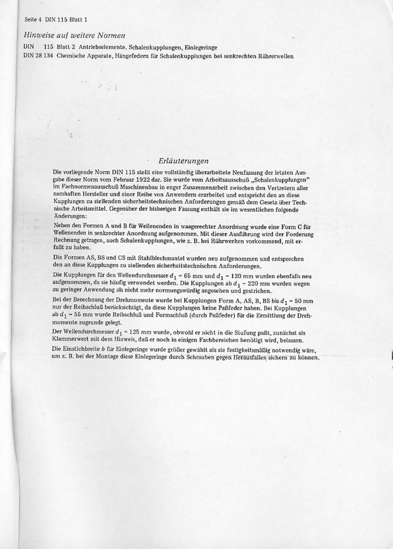
Die vorliegende Norm DIN 115 stellt eine vollständig überarbeitete Neufassung der letzten Ausgabe dieser Norm vom Februar 1922 dar. Sie wurde vom Arbeitsausschuß „Schalenkupplungen" im Fachnormenausschuß Maschinenbau in enger Zusammenarbeit zwischen den Vertretern aller namhaften Hersteller und einer Reihe von Anwendern erarbeitet und entspricht den an diese Kupplungen zu stellenden sicherheitstechnischen Anforderungen gemäß dem Gesetz über Technische Arbeitsmittel. Gegenüber der bisherigen Fassung enthält sie im wesentlichen folgende Änderungen:
Neben den Formen A und B für Wellenenden in waagerechter Anordnung wurde eine Form C für Wellenenden in senkrechter Anordnung aufgenommen. Mit dieser Ausführung wird der Forderung Rechnung getragen, auch Schalenkupplungen, wie z. B. bei Rührwerken vorkommend, mit erfaßt zu haben.
Die Formen AS, BS und CS mit Stahlblechmantel wurden neu aufgenommen und entsprechen den an diese Kupplungen zu stellenden sicherheitstechnischen Anforderungen.
Die Kupplungen für den Wellendurchmesser d1 = 65 mm und d1 = 120 mm wurden ebenfalls neu aufgenommen, da sie häufig verwendet werden. Die Kupplungen ab d1 = 220 mm wurden wegen zu geringer Anwendung als nicht mehr normungswürdig angesehen und gestrichen.
Bei der Berechnung der Drehmomente wurde bei Kupplungen Form A, AS, B, BS bis d1 = 50 mm nur der Reibschluß berücksichtigt, da diese Kupplungen keine Paßfeder haben. Bei Kupplungen ab d1 = 55 mm wurde Reibschluß und Formschiuß (durch Paßfeder) für die Ermittlung der Drehmomente zugrunde gelegt.
Der Wellendurchmesser d1 = 125 mm wurde, obwohl er nicht in die Stufung paßt, zunächst als Klammerwert mit dem Hinweis, daß er noch in einigen Fachbereichen benötigt wird, belassen.
Die Einstichbreite b für Einlegeringe wurde größer gewählt als sie festigkeitsmäßig notwendig wäre, um z. B. bei der Montage diese Einlegeringe durch Schrauben gegen Herausfallen sichern zu können.
4
Table 2. (Fortsetzung)
| Kranzbreite b | 180 | 200 | 224 | 250 | 280 | 315 | 355 | 400 | |||||||||||||
|---|---|---|---|---|---|---|---|---|---|---|---|---|---|---|---|---|---|---|---|---|---|
| zul. Abweichung ±2 | |||||||||||||||||||||
| Größte Riemebreite | ±3 | ||||||||||||||||||||
| Durchmesser d1 | 160 | 180 | 200 | 224 | 250 | 280 | 315 | 355 | |||||||||||||
| d2 max. | l | TN Nm | d2 max. | l | TN Nm | d2 max. | l | TN Nm | d2 max. | l | TN Nm | d2 max. | l | TN Nm | d2 max. | l | TN Nm | d2 max. | l | TN Nm | |
| 90 | 40 | 110 | 400 | 40 | 110 | 450 | 40 | 110 | 500 | 45 | 110 | 560 | 50 | 110 | 630 | 50 | 110 | 710 | 55 | 110 | 800 |
| 100 | 40 | 110 | 450 | 40 | 110 | 500 | 45 | 110 | 560 | 50 | 110 | 630 | 50 | 110 | 710 | 55 | 110 | 800 | |||
| 112 | 45 | 110 | 500 | 45 | 110 | 560 | 50 | 110 | 630 | 50 | 110 | 710 | 55 | 110 | 800 | ||||||
| 125 | 50 | 110 | 560 | 50 | 110 | 630 | 50 | 110 | 710 | 55 | 110 | 800 | |||||||||
| 140 | 50 | 110 | 630 | 50 | 110 | 710 | 55 | 110 | 800 | ||||||||||||
| 160 | 55 | 110 | 710 | 55 | 110 | 800 | |||||||||||||||
| 180 | 60 | 110 | 800 | ||||||||||||||||||
| 200 | 65 | 110 | 900 | 65 | 110 | 1000 | 65 | 140 | 1000 | 65 | 140 | 1200 | 65 | 160 | 1400 | 65 | 160 | 1600 | |||
| 224 | 65 | 110 | 1000 | 65 | 110 | 1100 | 65 | 140 | 1200 | 65 | 140 | 1400 | 65 | 160 | 1600 | 65 | 160 | 1800 | |||
| 250 | 65 | 110 | 1100 | 65 | 110 | 1200 | 65 | 140 | 1400 | 65 | 140 | 1600 | 65 | 160 | 1800 | 65 | 160 | 2000 | |||
| 280 | 70 | 110 | 1200 | 70 | 110 | 1400 | 70 | 140 | 1600 | 70 | 140 | 1800 | 70 | 160 | 2000 | 70 | 160 | 2200 | |||
| 315 | 70 | 110 | 1400 | 70 | 110 | 1600 | 70 | 140 | 1800 | 70 | 140 | 2000 | 70 | 160 | 2200 | 70 | 160 | 2500 | |||
| 355 | 75 | 110 | 1600 | 75 | 110 | 1800 | 75 | 140 | 2000 | 75 | 140 | 2200 | 75 | 160 | 2500 | 75 | 160 | 2800 | |||
| 400 | 75 | 110 | 560 | 75 | 120 | 630 | 80 | 140 | 710 | 85 | 140 | 800 | 85 | 160 | 900 | 85 | 140 | 1000 | |||
| 450 | 80 | 120 | 630 | 80 | 120 | 710 | 85 | 140 | 900 | 85 | 140 | 1000 | 85 | 160 | 1100 | 90 | 160 | 1200 | |||
| 500 | 80 | 120 | 710 | 80 | 120 | 800 | 85 | 140 | 900 | 85 | 140 | 1000 | 85 | 160 | 1100 | 90 | 160 | 1200 | |||
| 560 | 80 | 120 | 800 | 80 | 120 | 900 | 85 | 140 | 1000 | 85 | 140 | 1100 | 85 | 160 | 1200 | 90 | 160 | 1400 | |||
| 630 | 80 | 120 | 900 | 80 | 120 | 1000 | 85 | 140 | 1100 | 85 | 140 | 1200 | 85 | 160 | 1400 | 90 | 160 | 1600 | |||
| 200 | 100 | 200 | 1200 | 160 | 1400 | ||||||||||||||||
| 220 | 160 | 1400 | |||||||||||||||||||
| 220 | 160 | 1600 | |||||||||||||||||||
| 220 | 160 | 1800 | |||||||||||||||||||
| 220 | 160 | 2000 | |||||||||||||||||||
5
Seite 6 DIN 111
| Kranzbreite b | 180 | 200 | 224 | 250 | 280 | 315 | 355 | 400 | |||||||||||||||||
|---|---|---|---|---|---|---|---|---|---|---|---|---|---|---|---|---|---|---|---|---|---|---|---|---|---|
| z. Abweichung | ±2 | ±3 | |||||||||||||||||||||||
| Größe Riemenscheibe | 160 | 180 | 200 | 224 | 250 | 280 | 315 | 355 | |||||||||||||||||
| Boden-Durchmesser d1 | d2 max. | l | TN Nm | d2 max. | l | TN Nm | d2 max. | l | TN Nm | d2 max. | l | TN Nm | d2 max. | l | TN Nm | d2 max. | l | TN Nm | d2 max. | l | TN Nm | d2 max. | l | TN Nm | |
| 1T | 710 | 85 | 120 | 1000 | 85 | 120 | 1100 | 90 | 140 | 1200 | 95 | 160 | 1400 | 100 | 160 | 1600 | 105 | 180 | 1800 | 110 | 200 | 2000 | 115 | 220 | 2200 |
| 2T | 710 | 85 | 120 | 1100 | 90 | 120 | 1400 | 95 | 160 | 1600 | 100 | 160 | 1800 | 105 | 180 | 2000 | 110 | 180 | 2200 | 115 | 200 | 2500 | 120 | 220 | 2800 |
| 800 | 85 | 120 | 1100 | 90 | 160 | 1400 | 95 | 160 | 1600 | 100 | 160 | 1800 | 105 | 180 | 2000 | 110 | 180 | 2200 | 115 | 200 | 2500 | 120 | 200 | 2800 | |
| 800 | |||||||||||||||||||||||||
| 900 | 90 | 120 | 1200 | 95 | 120 | 1400 | 100 | 160 | 1600 | 100 | 160 | 1800 | 105 | 180 | 2000 | 110 | 180 | 2200 | 115 | 200 | 2500 | 120 | 200 | 2800 | |
| 900 | 90 | 120 | 1400 | 95 | 120 | 1600 | 100 | 160 | 1800 | 100 | 160 | 2000 | 105 | 180 | 2200 | 110 | 180 | 2500 | 115 | 200 | 2800 | 120 | 200 | 3200 | |
| 1000 | 90 | 120 | 1400 | 95 | 120 | 1600 | 100 | 160 | 1800 | 100 | 160 | 2000 | 105 | 180 | 2200 | 110 | 180 | 2500 | 115 | 200 | 2800 | 120 | 200 | 3200 | |
| 1000 | 95 | 140 | 1600 | 100 | 140 | 1800 | 100 | 160 | 2000 | 105 | 160 | 2200 | 110 | 180 | 2500 | 115 | 180 | 2800 | 120 | 200 | 3200 | 125 | 220 | 3600 | |
| 1120 | 95 | 140 | 1600 | 100 | 140 | 1800 | 100 | 160 | 2000 | 105 | 160 | 2200 | 110 | 180 | 2500 | 115 | 180 | 2800 | 120 | 200 | 3200 | 125 | 220 | 3600 | |
| 1120 | 100 | 140 | 1800 | 105 | 140 | 2000 | 110 | 160 | 2200 | 110 | 160 | 2500 | 115 | 180 | 2800 | 120 | 200 | 3200 | 125 | 200 | 3600 | 125 | 220 | 4000 | |
| 1250 | 100 | 140 | 1800 | 105 | 140 | 2000 | 110 | 160 | 2200 | 110 | 160 | 2500 | 115 | 180 | 2800 | 120 | 200 | 3200 | 125 | 200 | 3600 | 125 | 220 | 4000 | |
| 1250 | 105 | 160 | 2000 | 110 | 160 | 2200 | 110 | 160 | 2500 | 115 | 180 | 2800 | 120 | 200 | 3200 | 125 | 200 | 3600 | 125 | 220 | 4000 | 125 | 220 | 4500 | |
| 1400 | 105 | 160 | 2000 | 110 | 160 | 2200 | 110 | 160 | 2500 | 115 | 180 | 2800 | 120 | 200 | 3200 | 125 | 200 | 3600 | 125 | 220 | 4000 | 125 | 220 | 4500 | |
| 1400 | 105 | 160 | 2500 | 110 | 160 | 2800 | 115 | 180 | 3200 | 115 | 180 | 3600 | 120 | 200 | 4000 | 125 | 200 | 4500 | 125 | 220 | 5000 | 125 | 220 | 5600 | |
| 1600 | 105 | 160 | 2500 | 110 | 160 | 2800 | 115 | 180 | 3200 | 115 | 180 | 3600 | 120 | 200 | 4000 | 125 | 200 | 4500 | 125 | 220 | 5000 | ||||
| 1600 | 105 | 160 | 2800 | 110 | 160 | 3200 | 115 | 180 | 3600 | 115 | 180 | 4000 | 120 | 200 | 4500 | 125 | 200 | 5000 | 125 | 220 | 5600 | ||||
| 1800 | 105 | 160 | 2800 | 110 | 180 | 3200 | 115 | 180 | 3600 | 115 | 180 | 4000 | 120 | 200 | 4500 | 125 | 200 | 5000 | 125 | 220 | 5600 | ||||
| 1800 | 105 | 160 | 3200 | 110 | 180 | 3600 | 115 | 180 | 4000 | 115 | 180 | 4500 | 120 | 200 | 5000 | 125 | 200 | 5600 | 125 | 220 | 6300 | ||||
| 2000 | 105 | 160 | 3200 | 110 | 180 | 3600 | 115 | 180 | 4000 | 115 | 180 | 4500 | 120 | 200 | 5000 | 125 | 200 | 5600 | 125 | 220 | 6300 | ||||
| 2000 | 105 | 160 | 3200 | 110 | 180 | 3600 | 115 | 180 | 4000 | 115 | 180 | 4500 | 120 | 200 | 5000 | 125 | 200 | 5600 | 125 | 220 | 6300 | ||||
Das Nennmaß d2 ist in der Bezeichnung anzugeben.
6
预览内容由文件识别整理,表格、公式及文字请以原始文件为准。
原文图片预览
PAGE IMAGES

下载标准文件
DIN 168-1(1)
英语 · PDF · 6 页 · 7.96 MB