din-103-9(1)
ISO公制梯形螺纹 外螺纹和内螺纹的检验 量规尺寸和设计特征
din-103-9(1)
ISO metric trapezoidal screw threads - Gauging of external and internal threads - Gauge dimensions and design features
标准信息
STANDARD INFORMATION- 标准编号
- din-103-9(1)
- 所属分类
- DIN 德国标准
- 发布机构
- DIN
- 版本年份
- 1973
- 文件语言
- 英语
- 文件格式
- 文件页数
- 6 页
- 文件大小
- 47.49 MB
中文名称为参考译名,文件语言以原文为准。
· 更新:
标准简介
OVERVIEW中文简介
该标准规定了ISO公制梯形螺纹量规的尺寸和设计特征,包括螺纹轮廓、公差带及量规几何参数。它适用于制造用于检验外螺纹和内螺纹的量规,如通止规、环规和卡规。
English summary
This standard specifies the dimensions and design features of gauges for ISO metric trapezoidal screw threads, including thread profiles, tolerance zones, and gauge geometry. It applies to the manufacturing of gauges used for inspecting external and internal threads, such as go/no-go gauges, ring gauges, and calliper gauges.
以上为根据文件整理的内容简介。
相关标签
标准内容预览
DOCUMENT PREVIEWISO metric trapezoidal screw threads
Gauging of external and internal threads
Gauge dimensions and design features
Metrisches ISO-Trapezgewinde; Lehren für Bolzen- und Muttergewinde, Lehrenmaße und Baumerkmale
Supersedes August 1973 edition.
In keeping with current practice in standards published by the International Organization for Standardization (ISO), a comma has been used throughout as the decimal marker.
This standard gives specifications necessary for manufacturing gauges for ISO metric trapezoidal screw threads.
General specifications relating to the gauging system, nomenclature, gauging of workpieces and handling of gauges have not been separately standardized for gauges for trapezoidal screw threads; for these, DIN 13 Part 16 and Part 18 shall be applied as appropriate.
This standard specifies only the required gauge dimensions and design features. The manufacturing tolerances have been increased in comparison with those specified in DIN 13 Part 17 by about 45 % in order to compensate for the effect of the steeper flanks of the ISO metric trapezoidal thread.
Contents
| Page | Page |
|---|---|
| 1 Thread profiles ... 2 | 4 Tolerances and permissible wear ... 10 |
| 1.1 Profiles with complete flanks ... 2 | 5 General design features of screw gauges ... 11 |
| 1.2 Profiles with truncated flanks ... 3 | 5.1 Gauges for workpiece external threads ... 11 |
| 2 Tolerance zones ... 4 | 5.1.1 Solid Go screw ring gauge ... 11 |
| 2.1 Tolerance zones for pitch diameter ... 4 | 5.1.2 Go screw calliper gauge ... 11 |
| 2.2 Tolerance zones for plain gauges ... 5 | 5.1.3 Setting plug for Go screw calliper gauge ... 11 |
| 3 Calculation of gauge dimensions ... 6 | 5.1.4 Not Go screw calliper gauge ... 11 |
| 3.1 Gauges for workpiece external threads ... 6 | 5.1.5 Solid Not Go screw ring gauge ... 11 |
| 3.2 Gauges for the major diameter ... 9 | 5.2 Gauges for workpiece internal threads ... 11 |
| 3.3 Gauges for workpiece internal threads ... 9 | 5.2.1 Go screw plug gauge ... 11 |
| 3.4 Gauges for the minor diameter ... 9 | 5.2.2 Not Go screw plug gauge ... 11 |
| 5.3 Start of thread ... 12 |
Continued on pages 2 to 12
1
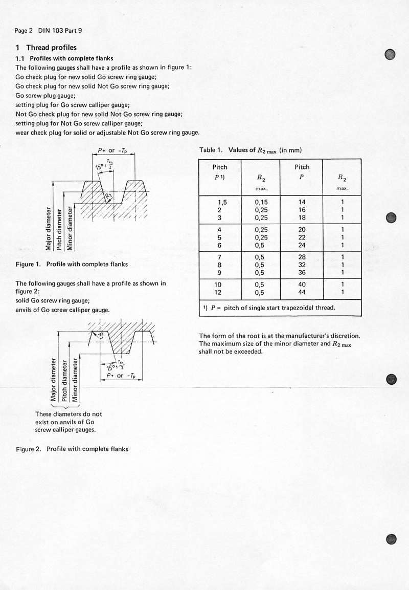
1 Thread profiles
1.1 Profiles with complete flanks
The following gauges shall have a profile as shown in figure 1:
- Go check plug for new solid Go screw ring gauge;
- Go check plug for new solid Not Go screw ring gauge;
- Go screw plug gauge;
- setting plug for Go screw calliper gauge;
- Not Go check plug for new solid Not Go screw ring gauge;
- setting plug for Not Go screw calliper gauge;
- wear check plug for solid or adjustable Not Go screw ring gauge.
Figure 1. Profile with complete flanks
The following gauges shall have a profile as shown in figure 2:
- solid Go screw ring gauge;
- anvils of Go screw calliper gauge.
Figure 2. Profile with complete flanks
These diameters do not exist on anvils of Go screw calliper gauges.
| Pitch P 1) | R2 max. | Pitch P | R2 max. |
|---|---|---|---|
| 1,5 | 0,15 | 14 | 1 |
| 2 | 0,25 | 16 | 1 |
| 3 | 0,25 | 18 | 1 |
| 4 | 0,25 | 20 | 1 |
| 5 | 0,25 | 22 | 1 |
| 6 | 0,5 | 24 | 1 |
| 7 | 0,5 | 28 | 1 |
| 8 | 0,5 | 32 | 1 |
| 9 | 0,5 | 36 | 1 |
| 10 | 0,5 | 40 | 1 |
| 12 | 0,5 | 44 | 1 |
1) P = pitch of single start trapezoidal thread.
The form of the root is at the manufacturer's discretion. The maximum size of the minor diameter and R2 max shall not be exceeded.
2
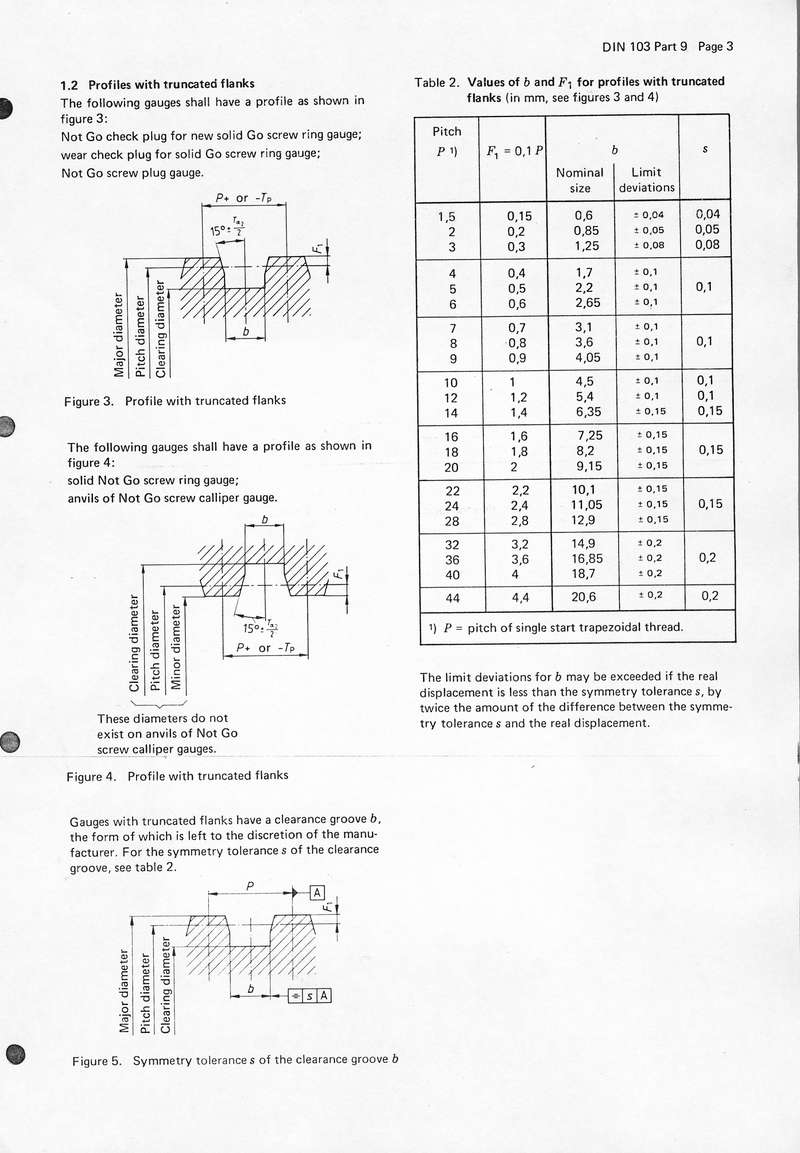
1.2 Profiles with truncated flanks
The following gauges shall have a profile as shown in figure 3:
Not Go check plug for new solid Go screw ring gauge; wear check plug for solid Go screw ring gauge; Not Go screw plug gauge.
Figure 3. Profile with truncated flanks
The following gauges shall have a profile as shown in figure 4:
solid Not Go screw ring gauge; anvils of Not Go screw calliper gauge.
Figure 4. Profile with truncated flanks
Gauges with truncated flanks have a clearance groove b, the form of which is left to the discretion of the manufacturer. For the symmetry tolerance s of the clearance groove, see table 2.
Figure 5. Symmetry tolerance s of the clearance groove b
| Pitch P 1) | F1 = 0,1 P | b | s | |
|---|---|---|---|---|
| Nominal size | Limit deviations | |||
| 1,5 | 0,15 | 0,6 | ± 0,04 | 0,04 |
| 2 | 0,2 | 0,85 | ± 0,05 | 0,05 |
| 3 | 0,3 | 1,25 | ± 0,08 | 0,08 |
| 4 | 0,4 | 1,7 | ± 0,1 | 0,1 |
| 5 | 0,5 | 2,2 | ± 0,1 | |
| 6 | 0,6 | 2,65 | ± 0,1 | |
| 7 | 0,7 | 3,1 | ± 0,1 | 0,1 |
| 8 | 0,8 | 3,6 | ± 0,1 | |
| 9 | 0,9 | 4,05 | ± 0,1 | |
| 10 | 1 | 4,5 | ± 0,1 | 0,1 |
| 12 | 1,2 | 5,4 | ± 0,1 | 0,1 |
| 14 | 1,4 | 6,35 | ± 0,15 | 0,15 |
| 16 | 1,6 | 7,25 | ± 0,15 | 0,15 |
| 18 | 1,8 | 8,2 | ± 0,15 | |
| 20 | 2 | 9,15 | ± 0,15 | |
| 22 | 2,2 | 10,1 | ± 0,15 | 0,15 |
| 24 | 2,4 | 11,05 | ± 0,15 | |
| 28 | 2,8 | 12,9 | ± 0,15 | |
| 32 | 3,2 | 14,9 | ± 0,2 | 0,2 |
| 36 | 3,6 | 16,85 | ± 0,2 | |
| 40 | 4 | 18,7 | ± 0,2 | |
| 44 | 4,4 | 20,6 | ± 0,2 | 0,2 |
| 1) P = pitch of single start trapezoidal thread. | ||||
The limit deviations for b may be exceeded if the real displacement is less than the symmetry tolerance s, by twice the amount of the difference between the symmetry tolerance s and the real displacement.
3
2 Tolerance zones
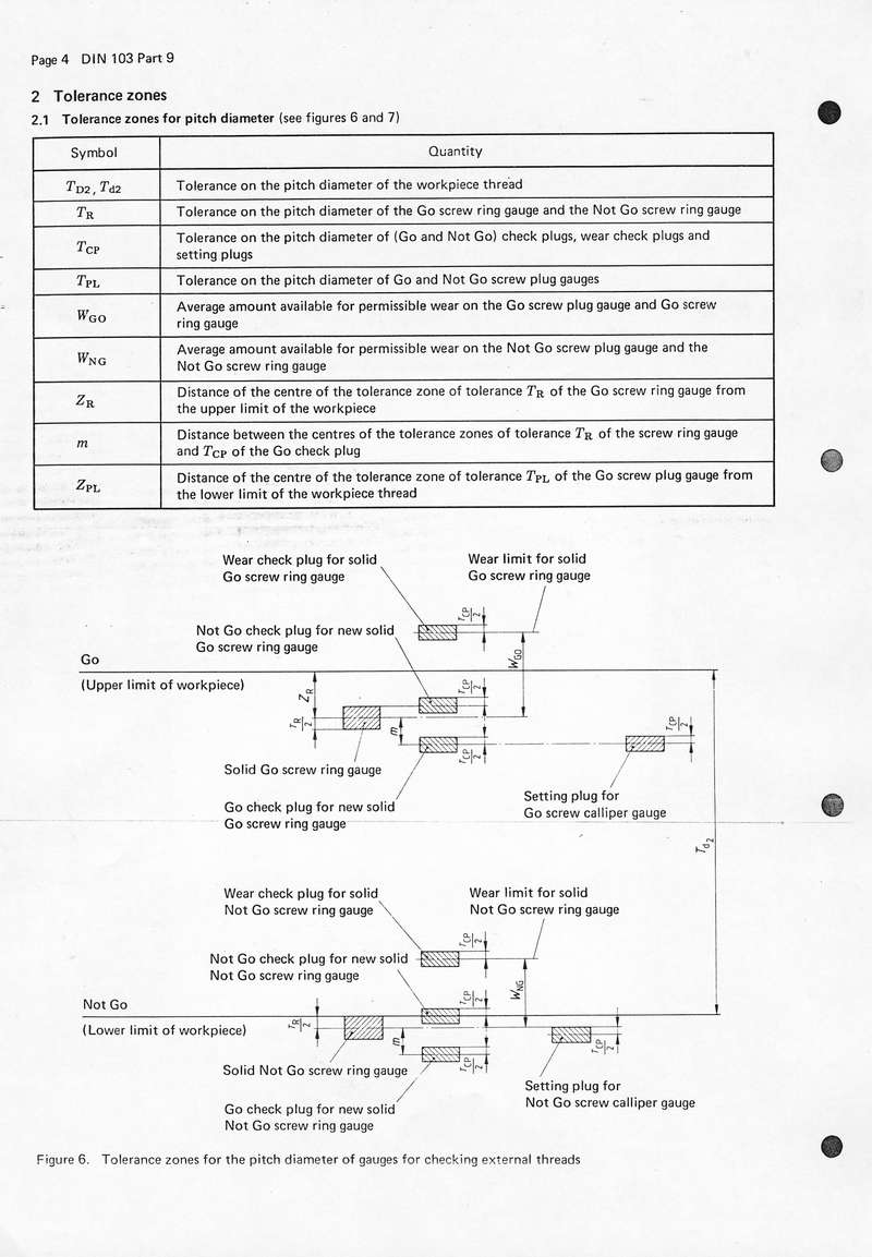
2.1 Tolerance zones for pitch diameter (see figures 6 and 7)
| Symbol | Quantity |
|---|---|
| TD2, Td2 | Tolerance on the pitch diameter of the workpiece thread |
| TR | Tolerance on the pitch diameter of the Go screw ring gauge and the Not Go screw ring gauge |
| TCP | Tolerance on the pitch diameter of (Go and Not Go) check plugs, wear check plugs and setting plugs |
| TPL | Tolerance on the pitch diameter of Go and Not Go screw plug gauges |
| WGO | Average amount available for permissible wear on the Go screw plug gauge and Go screw ring gauge |
| WNG | Average amount available for permissible wear on the Not Go screw plug gauge and the Not Go screw ring gauge |
| ZR | Distance of the centre of the tolerance zone of tolerance TR of the Go screw ring gauge from the upper limit of the workpiece |
| m | Distance between the centres of the tolerance zones of tolerance TR of the screw ring gauge and TCP of the Go check plug |
| ZPL | Distance of the centre of the tolerance zone of tolerance TPL of the Go screw plug gauge from the lower limit of the workpiece thread |
Figure 6. Tolerance zones for the pitch diameter of gauges for checking external threads
4
The pitch diameter of screw ring gauges can be measured directly where it cannot be better checked with check plugs. In order to ensure that a screw ring gauge that has been found to be correct by direct measurement will also be found correct when checked with a Go check plug, it is necessary to shift the pitch diameter tolerance zone of the Go check plug downwards by an amount m, in relation to the pitch diameter tolerance zone of the screw ring gauge (see figure 6). The values specified in table 7 for m represent the sum of the diametral equivalents of the average errors that are likely to occur in the pitch and the flank angles of the check plug and of the screw ring gauge, in relation to the specified tolerances on these thread parameters.
Figure 7. Tolerance zones for the pitch diameter of gauges for checking internal threads
2.2 Tolerance zones for plain gauges (see figures 8 and 9)
| Symbol | Quantity |
|---|---|
| TD1 | Tolerance on the minor diameter of the workpiece internal thread |
| Td | Tolerance on the major diameter of the workpiece external thread |
| H1 | Tolerance for plug gauges |
| H2 | Tolerance for calliper gauges and ring gauges |
| Z1 | Distance of the centre of the tolerance zone of tolerance H1 of Go plug gauges from the lower limit of the workpiece thread |
| Z2 | Distance of the centre of the tolerance zone of tolerance H2 of Go calliper gauges or Go ring gauges from the upper limit of the workpiece thread |
Tolerance zones for check gauges for calliper gauges shall be selected in accordance with DIN 7162.
5
3 Calculation of gauge dimensions
Figure 8. Tolerance zones for gauges for checking the major diameter of external threads
Figure 9. Tolerance zones for gauges for checking the minor diameter of internal threads
3.1 Gauges for workpiece external threads
In table 3 on pages 7 and 8
d3, D4, d, d2 and D1 are nominal thread diameters;
Td2 is the tolerance on the pitch diameter as specified in DIN 103 Part 3;
A0 is the fundamental deviation for the pitch diameter for the appropriate tolerance position as specified in DIN 103 Part 3.
(A0 shall be inserted in the table 3 equations omitting the sign specified for the fundamental deviations. For tolerance position h, A0 = 0)
6
预览内容由文件识别整理,表格、公式及文字请以原始文件为准。
原文图片预览
PAGE IMAGES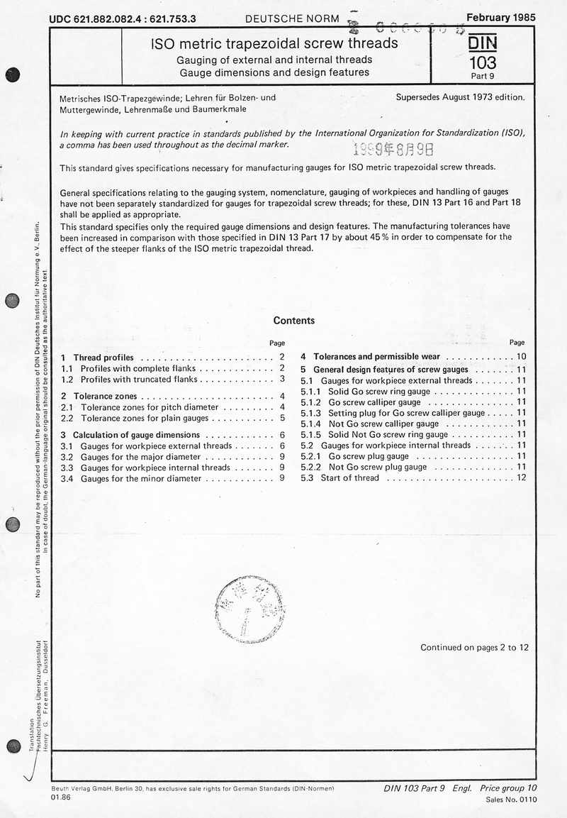
下载标准文件
din-103-9(1)
英语 · PDF · 6 页 · 47.49 MB