DIN 250(1)
工件上的圆角及其在技术图纸中的表示
DIN 250(1)
Radii on workpieces and their representation in technical drawings
标准信息
STANDARD INFORMATION- 标准编号
- DIN 250(1)
- 所属分类
- DIN 德国标准
- 发布机构
- DIN
- 版本年份
- 2002
- 文件语言
- 英语
- 文件格式
- 文件页数
- 6 页
- 文件大小
- 10.69 MB
中文名称为参考译名,文件语言以原文为准。
· 更新:
标准简介
OVERVIEW中文简介
该标准规定了工件上圆角的尺寸系列,旨在减少制造和检验所需的刀具、量具和测量仪器的数量。它提供了圆角在技术图纸中表示的示例,并指定了符合R5、R10和R20优先数系的圆角值。
English summary
This standard specifies the sizes of radii on workpieces to limit the number of tools, gauges, and measuring instruments required for manufacture and checking. It provides examples of representing these radii in technical drawings and defines preferred values based on R5, R10, and R20 series.
以上为根据文件整理的内容简介。
相关标签
标准内容预览
DOCUMENT PREVIEWDEUTSCHE NORM
April 2002
|
Radii on workpieces and their representation in technical drawings |
DIN 250 |
ICS 17.040.30
Supersedes
July 1972 edition.
Radien
In keeping with current practice in standards published by the International Organization for Standardization (ISO), a comma has been used throughout as the decimal marker.
Foreword
This standard has been prepared by Technical Committee Technisches Zeichnen of the Normenausschuss Technische Grundlagen (Fundamentals in Technology Standards Committee).
The objective of this standard is to limit the number of tools, gauges and measuring instruments needed for the manufacture and checking of radii. Therefore, only the radii specified in this standard should be used in the design of workpieces.
Amdments
This standard differs from the July 1972 edition in that it has been editorially revised and the examples have been brought into line with current practice.
Previous editions
DIN 250: 1922-01, 1924-04, 1939-12, 1972-07.
All dimensions are in millimetres.
1 Scope
This standard specifies radii on workpieces and gives examples of their representation in technical drawings. The radii conform to the preferred number series R 5, R 10, and R 20 as in DIN 323-1, with some of the values taken from the corresponding rounded value series R" 5, R' 10, and R" 10.
2 Normative references
This standard incorporates, by dated or undated reference, provisions from other publications. These normative references are cited at the appropriate places in the text, and the titles of the publications are listed below. For dated references, subsequent amendments to or revisions of any of these publications apply to this standard only when incorporated in it by amendment or revision. For undated references, the latest edition of the publication referred to applies.
DIN 323-1 Preferred numbers and preferred number series – Basic, calculated and rounded values
DIN 406-11 Engineering drawing practice – Dimensioning – Principles of application
Continued on pages 2 and 3.
Translation by DIN-Sprachendienst.
In case of doubt, the German-language original should be consulted as the authoritative text.
© No part of this translation may be reproduced without the prior permission of DIN Deutsches Institut für Normung e. V., Berlin. Beuth Verlag GmbH, 10772 Berlin, Germany, has the exclusive right of sale for German Standards (DIN-Normen).
Ref. No. DIN 250 : 2002-04
English price group 05 Sales No. 0105
03.03
1
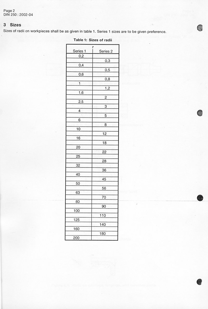
3 Sizes
Sizes of radii on workpieces shall be as given in table 1. Series 1 sizes are to be given preference.
| Series 1 | r | Series 2 |
|---|---|---|
| 0,2 | ||
| 0,3 | ||
| 0,4 | ||
| 0,5 | ||
| 0,6 | ||
| 0,8 | ||
| 1 | ||
| 1,2 | ||
| 1,6 | ||
| 2 | ||
| 2,5 | ||
| 3 | ||
| 4 | ||
| 5 | ||
| 6 | ||
| 8 | ||
| 10 | ||
| 12 | ||
| 16 | ||
| 18 | ||
| 20 | ||
| 22 | ||
| 25 | ||
| 28 | ||
| 32 | ||
| 36 | ||
| 40 | ||
| 45 | ||
| 50 | ||
| 56 | ||
| 63 | ||
| 70 | ||
| 80 | ||
| 90 | ||
| 100 | ||
| 110 | ||
| 125 | ||
| 140 | ||
| 160 | ||
| 180 | ||
| 200 |
2
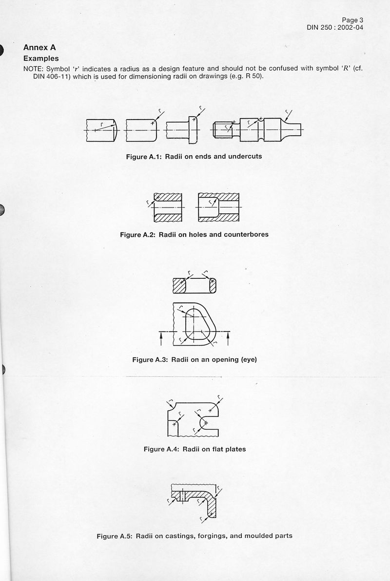
Annex A Examples
NOTE: Symbol 'r' indicates a radius as a design feature and should not be confused with symbol 'R' (cf. DIN 406-11) which is used for dimensioning radii on drawings (e.g. R 50).
Figure A.1: Radii on ends and undercuts
Figure A.2: Radii on holes and counterbores
Figure A.3: Radii on an opening (eye)
Figure A.4: Radii on flat plates
Figure A.5: Radii on castings, forgings, and moulded parts
3
3 Toleranzen der Kegelhülse
| Form C | D | C |
| d0 | dC | d1 |
| lp | 1 bis 2,5 | ½[(dC−d0)−AT0] |
| Form D | D | C |
| d0 | dC | d1 |
| lp | 1 bis 2,5 | ½[(dC−d0)−AT0] |
| Metrische Kegelhülse Form C Größe |
Morsekegelhülse Form C, D, CK oder DK Größe |
||||||||
|---|---|---|---|---|---|---|---|---|---|
| 4 | 6 | 0 | 1 | 2 | 3 | 4 | 5 | 6 | |
| Verjüngung | 1 : 20 = 0,05 | 1 : 19,212 = 0,05205 | 1 : 20,047 = 0,04988 | 1 : 20,020 = 0,04995 | 1 : 19,922 = 0,05020 | 1 : 19,254 = 0,05194 | 1 : 19,002 = 0,05263 | 1 : 19,180 = 0,05214 | |
| d1 | 4 | 6 | 9,045 | 12,065 | 17,780 | 23,825 | 31,267 | 44,399 | 63,348 |
| dC − dD | 0,8 | 1,2 | 2,134 | 2,195 | 2,647 | 3,414 | 4,467 | 5,895 | 8,238 |
| lp | 16 | 24 | 41 | 44 | 53 | 68 | 86 | 112 | 158 |
| AT 4 | 0,003 | 0,003 | 0,003 | 0,004 | 0,004 | 0,004 | 0,005 | 0,006 | 0,008 |
| AT 5 | 0,004 | 0,005 | 0,005 | 0,006 | 0,007 | 0,007 | 0,009 | 0,009 | 0,013 |
| ATD AT 6 | 0,006 | 0,008 | 0,008 | 0,009 | 0,011 | 0,011 | 0,014 | 0,014 | 0,020 |
| AT 7 | 0,010 | 0,012 | 0,013 | 0,014 | 0,017 | 0,017 | 0,022 | 0,022 | 0,032 |
| AT 8 | 0,016 | 0,019 | 0,021 | 0,022 | 0,027 | 0,027 | 0,034 | 0,035 | 0,049 |
4
Normative und informative Verweise
| Metrische Kegelhülse Form C oder D Größe |
||||||||
|---|---|---|---|---|---|---|---|---|
| 80 | 100 | 120 | (140) | 160 | (180) | 200 | ||
| Verjüngung | 1 : 20 = 0,05 | |||||||
| d1 | 80 | 100 | 120 | 140 | 160 | 180 | 200 | |
| dC - dD | 8,2 | 9,6 | 11 | 12,4 | 13,8 | 15,2 | 16,6 | |
| lP | 164 | 192 | 220 | 248 | 276 | 304 | 332 | |
| ATD | AT 3 | 0,004 | 0,005 | 0,006 | 0,006 | 0,006 | 0,006 | 0,007 |
| AT 4 | 0,007 | 0,008 | 0,009 | 0,010 | 0,009 | 0,010 | 0,010 | |
| AT 5 | 0,010 | 0,012 | 0,014 | 0,016 | 0,014 | 0,015 | 0,017 | |
| AT 6 | 0,016 | 0,019 | 0,022 | 0,025 | 0,022 | 0,024 | 0,027 | |
| AT 7 | 0,026 | 0,031 | 0,035 | 0,031 | 0,035 | 0,038 | 0,042 | |
| AT 8 | 0,041 | 0,048 | 0,055 | 0,062 | 0,055 | 0,061 | 0,066 | |
| Die Differenz der Istmaße dC und dD in den Meßebenen C und D soll nicht größer als der angegebene Wert dC - dD und nicht kleiner als dC - dD - ATD sein. Die Toleranz ATD errechnet sich aus der Kegelwinkeltoleranz AT nach der Formel ATD = ATα · lP / 106, siehe auch DIN 7178 Teil 1. Die Kegelmeßlängen lP der Kegel ME 4 bis ME 6 und MK 0 bis MK 6 sind gegenüber DIN 228 Teil 1 verkürzt, siehe auch Erläuterungen. Die Toleranzen schließen die Ungeradheit der Mantellinie sowie die Unrundheit ein. |
||||||||
Zitierte Normen
DIN 228 Teil 1 Morsekegel und Metrische Kegel; Kegelschäfte
DIN 7168 Teil 1 Allgemeintoleranzen; Längen- und Winkellmaße
DIN 7178 Teil 1 Kegelstoleranz- und Kegelmaßsystem für Kegel von Verjüngung C = 1 : 3 bis 1 : 500 und Längen von 6 bis 630 mm; Kegelstoleranzsystem
Weitere Normen
ISO 296 – 1974 Machine tools – Self-holding tapers for tool shanks
Frühere Ausgaben
DIN 231: 07.22, 09.24; DIN 233: 07.22, 07.25; DIN 228: 07.22, 07.25, 03.56; DIN 228 Teil 1 und Teil 2: 10.43; DIN 228 Teil 2: 01.59x, 01.81, 07.82
Änderungen
Gegenüber der Ausgabe Juli 1982 wurden folgende Änderungen vorgenommen:
a) Der Inhalt der Norm wurde um Ausführungsvarianten von Morsekegelhülsen (MK 2 bis MK 6) für zentrale Kühschmierstoffzuführung erweitert.
Erläuterungen
Diese Norm stimmt weitgehend sachlich überein mit der von der International Organization for Standardization (ISO) herausgegebenen Internationalen Norm ISO 296 – 1974 **)
E: Machine tools – Self-holding tapers for tool shanks
F: Machines-outils – Cônes pour emmanchements d'outils à faible conicité
D: Maschinenwerkzeuge – Selbsthaftende Kegel für Werkzeugkegel
ISO 296 – 1974 enthält keine Festlegungen über Grenzabmaße zu z, Metrische Kegel 140 und 180, l7 und Bezeichnungsbeispiele. Festlegungen über zentrale Kühschmierstoffzuführung fehlen ebenfalls.
In Tabelle 2 sind Toleranzklassen – AT 4 bis AT 8 für alle Kegelgrößen – AT 3 zusätzlich für ME 80 bis ME 200, enthalten. Aus prüftechnischen Gründen ist das Bezugsmaß dc innerhalb der Kegelhülse, das Maß lP für ME 4 und ME 6 sowie MK 0 bis MK 6 ist gegenüber DIN 228 Teil 1 verkürzt.
Internationale Patentklassifikation
B 23 B 31/06 B 23 B 51/12 B 23 Q 3/12 B 23 Q 3/14 G 01 M 19/00
**) ISO-Normen sind in englischer und französischer Fassung beziehbar durch: Beuth Verlag GmbH, Burggrafenstr. 6, 1000 Berlin 30
5
Seite 6 DIN 228 Teil 1
| Metrischer Kegelschaft Form A Größe |
Morsekegelschaft Form A, B, AK oder BK Größe |
||||||||||
|---|---|---|---|---|---|---|---|---|---|---|---|
| 4 | 6 | 0 | 1 | 2 | 3 | 4 | 5 | 6 | |||
| Verjüngung | 1 : 20 = 0,05 | 1 : 19,212 = 0,05205 | 1 : 20,047 = 0,04988 | 1 : 20,020 = 0,04995 | 1 : 19,922 = 0,05020 | 1 : 19,254 = 0,05194 | 1 : 19,002 = 0,05263 | 1 : 19,180 = 0,05214 | |||
| dA = d1 | 4 | 6 | 9,045 | 12,065 | 17,780 | 23,825 | 31,267 | 44,399 | 63,348 | ||
| dA − dB | 0,95 | 1,3 | 2,238 | 2,245 | 2,697 | 3,464 | 4,519 | 5,999 | 8,446 | ||
| lP | 19 | 26 | 43 | 45 | 54 | 69 | 87 | 114 | 162 | ||
| ATD | AT 4 | 0,002 | 0,003 | 0,003 | 0,004 | 0,004 | 0,004 | 0,005 | 0,006 | 0,006 | |
| AT 5 | 0,004 | 0,004 | 0,005 | 0,006 | 0,007 | 0,007 | 0,009 | 0,009 | 0,010 | ||
| AT 6 | 0,006 | 0,007 | 0,009 | 0,009 | 0,011 | 0,011 | 0,014 | 0,014 | 0,016 | ||
| AT 7 | 0,010 | 0,010 | 0,014 | 0,014 | 0,017 | 0,017 | 0,022 | 0,023 | 0,026 | ||
| AT 8 | 0,015 | 0,016 | 0,022 | 0,023 | 0,027 | 0,028 | 0,035 | 0,036 | 0,041 | ||
| Metrischer Kegelschaft Form A oder B Größe |
|||||||||||
| 80 | 100 | 120 | (140) | 160 | (180) | 200 | |||||
| Verjüngung | 1 : 20 = 0,05 | ||||||||||
| dA = d1 | 80 | 100 | 120 | 140 | 160 | 180 | 200 | ||||
| dA − dB | 8,2 | 9,6 | 11 | 12,4 | 13,8 | 15,2 | 16,6 | ||||
| lP | 164 | 192 | 220 | 248 | 276 | 304 | 332 | ||||
| ATD | AT 3 | 0,004 | 0,005 | 0,006 | 0,006 | 0,006 | 0,006 | 0,007 | |||
| AT 4 | 0,007 | 0,008 | 0,009 | 0,010 | 0,009 | 0,010 | 0,010 | ||||
| AT 5 | 0,010 | 0,012 | 0,014 | 0,016 | 0,014 | 0,015 | 0,017 | ||||
| AT 6 | 0,016 | 0,019 | 0,022 | 0,025 | 0,022 | 0,024 | 0,027 | ||||
| AT 7 | 0,026 | 0,031 | 0,035 | 0,040 | 0,035 | 0,038 | 0,042 | ||||
| AT 8 | 0,041 | 0,048 | 0,055 | 0,062 | 0,055 | 0,061 | 0,066 | ||||
Die Differenz der Istmaße dA und dB in den Meßebenen A und B soll nicht kleiner als der angegebene Wert dA − dB und nicht größer als dA − dB + ATD sein.
Die Toleranz ATD errechnet sich aus der Kegelwinkeltoleranz AT, nach der Formel ATD = ATα · lP / 106, siehe auch DIN 7178 Teil 1.
Die Kegelmeßlänge lP ist so gewählt, daß der Abstand der Meßebene B vom kleinen Durchmesser des Kegels ungefähr dem Abstand a der Meßebene A vom großen Durchmesser des Kegels entspricht.
Die Toleranzen der Kegelwinkel schließen die Ungeradheit der Mantellinie sowie die Unrundheit ein.
6
预览内容由文件识别整理,表格、公式及文字请以原始文件为准。
原文图片预览
PAGE IMAGES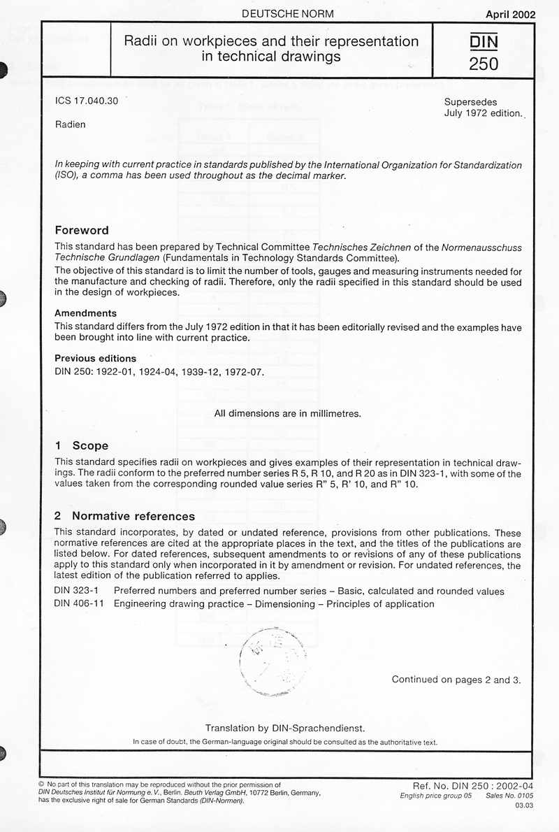

下载标准文件
DIN 250(1)
英语 · PDF · 6 页 · 10.69 MB