DIN 267-2-1984.11(1)
紧固件 技术交货条件 设计和尺寸精度
DIN 267-2-1984.11(1)
Fasteners Technical delivery conditions Design and dimensional accuracy
标准信息
STANDARD INFORMATION- 标准编号
- DIN 267-2-1984.11(1)
- 所属分类
- DIN 德国标准
- 发布机构
- DIN
- 版本年份
- 1980
- 文件语言
- 英语
- 文件格式
- 文件页数
- 6 页
- 文件大小
- 15.89 MB
中文名称为参考译名,文件语言以原文为准。
· 更新:
标准简介
OVERVIEW中文简介
该标准规定了紧固件(如螺栓、螺钉和螺母)的技术交货条件,包括设计和尺寸精度要求。它补充了DIN ISO 4759 Part 1,适用于引用DIN 267 Part 2的产品标准,涵盖螺纹公差、表面粗糙度及测量方法。
English summary
This standard specifies the technical delivery conditions for fasteners, including design and dimensional accuracy. It supplements DIN ISO 4759 Part 1 and applies to product standards referencing DIN 267 Part 2, covering thread tolerances, surface roughness, and measurement methods.
以上为根据文件整理的内容简介。
相关标签
标准内容预览
DOCUMENT PREVIEWFasteners
Technical delivery conditions
Design and dimensional accuracy
| Mechanische Verbindungselemente; technische Lieferbedingungen; Ausführung und Maßgenauigkeit | This standard, together with DIN ISO 4759 Part 1, May 1980 edition, supersedes April 1968 edition. |
In keeping with current practice in standards published by the International Organization for Standardization (ISO), a comma has been used throughout as the decimal marker.
The previous edition of April 1968 of DIN 267 Part 2 has been partly superseded by the May 1980 edition of DIN ISO 4759 Part 1, which incorporates International Standard ISO 4759/1 — 1978 and serves as the basis or reference standard for product standards (dimensional standards) dealing with bolts, screws and nuts (see also Explanatory notes). The international standard primarily applies to bolts, screws and nuts with metric thread, but can, like DIN 267 Part 2, also be applied as appropriate to other products such as tapping screws and wood screw.
1 Scope and field of application
This standard supplements DIN ISO 4759 Part 1 and applies to those product standards (dimensional standards) in which DIN 267 Part 2 is referred to, e.g. with regard to the surface roughness of bolts, screws and nuts.
Note. The illustrations providing information on the tolerances, which were included in the April 1968 edition of DIN 267 Part 2, have to a large extent been replaced by the specifications given in ISO 4759 Part 1. In this standard, only individual characteristics of fasteners, e.g. bolt lengths, have been tolerated, so that the individual product types are not illustrated, or are only shown in part. To simplify the use of both these standards, the previous illustrations have been assembled in Supplement 1 to DIN 267 Part 2.
In cases of doubt, the specifications given in the product standard or in ISO 4759 Part 1 and in this standard shall apply.
It is recommended that Standards ISO 4759 Part 1 and DIN 267 Part 2 should also be used for non-standardized fasteners and that these standards should be referred to giving details of the respective product grade in the purchase order documents.
2 General
ISO 4759 Part 1 shall apply with regard to the design and dimensional accuracy of fasteners (primarily of bolts, screws and nuts), unless other specifications are given in the individual product standards or purchase order documents. ISO 4759 Part 1 covers bolts, screws and nuts with nominal thread diameters from 1,6 up to and including 150 mm, assigned to the following three product grades:
product grade A (previously design m, medium),
product grade B (previously design mg, medium coarse) and
product grade C (previously design g, coarse),
the reference dimension for allocating the tolerances being the individual dimension specified in the relevant product standards (dimensional standards).
DIN 7168 Part 1 shall apply with regard to those dimensions which are not tolerated in this standard, nor in ISO 4759 Part 1, nor in the product standards (dimensional standards). In these cases, DIN 7168, accuracy grade m shall apply with regard to general tolerances assigned to product grade A (previously design m);
DIN 7168, accuracy grade g shall apply with regard to general tolerances assigned to product grades B and C (previously designs mg and g).
Note. The change of the previous nomenclature designs m, mg and g, to product grades A, B and C is based on the international specifications given in ISO 4759 Part 1. It is not necessary to amend existing documents accordingly.
A further product grade F (previously referred to as design f, fine) is specified in DIN 267 Part 6. This can be used, if required, for bolts, screws and nuts of up to 3 mm nominal thread diameter and takes into account the particular requirements of precision engineering.
Continued on pages 2 to 4
1
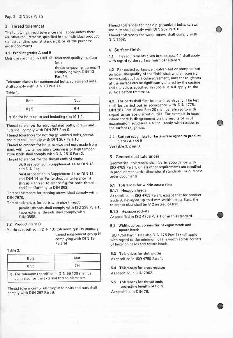
3 Thread tolerances
The following thread tolerances shall apply unless there are other requirements specified in the individual product standards (dimensional standards) or in the purchase order documents.
3.1 Product grades A and B
Metric as specified in DIN 13: tolerance quality medium (m);
thread engagement group N complying with DIN 13 Part 14.
Tolerance classes for commercial bolts, screws and nuts shall comply with DIN 13 Part 14.
Table 1.
| Bolt | Nut |
|---|---|
| 6 g 1) | 6 H |
| 1) 6h for bolts up to and including size M 1,4. | |
Thread tolerances for electroplated bolts, screws and nuts shall comply with DIN 267 Part 9.
Thread tolerances for hot dip galvanized bolts, screws and nuts shall comply with DIN 267 Part 10.
Thread tolerances for bolts, screws and nuts made from steels with low temperature toughness or high temperature steels shall comply with DIN 2510 Part 2.
Thread tolerances for the thread ends of studs:
Sk 6 as specified in Supplement 14 to DIN 13 and DIN 14;
Sn 4 as specified in Supplement 14 to DIN 13 and DIN 14 or Fo (without interference fit thread = thread tolerance 6 g for both thread ends) conforming to DIN 962.
Thread tolerances for tapping screws shall comply with DIN 7970.
Thread tolerances for parts with pipe thread:
parallel threads shall comply with ISO 228 Part 1;
taper external threads shall comply with DIN 3858.
3.2 Product grade C
Metric as specified in DIN 13: tolerance quality coarse g;
thread engagement group N complying with DIN 13 Part 14.
Table 2.
| Bolt | Nut |
|---|---|
| 8 g 1) | 7 H |
| 1) The tolerances specified in DIN 59 130 shall be permitted for the external thread diameters. | |
Thread tolerances for electroplated bolts and nuts shall comply with DIN 267 Part 9.
Thread tolerances for hot dip galvanized bolts, screws and nuts shall comply with DIN 267 Part 10.
Thread tolerances for wood screws shall comply with DIN 7998.
4 Surface finish
4.1 The requirements given in subclause 4.4 shall apply with regard to the surface finish of fasteners.
4.2 For coated surfaces, e.g. galvanized or phosphatized surfaces, the quality of the finish shall where necessary be the subject of particular agreement, since the roughness of the surface can be significantly altered by the coating and the values specified in subclause 4.4 apply to the surface before treatment.
4.3 The parts shall first be examined visually. The test shall be carried out in accordance with DIN 4775. DIN 267 Part 19 and Part 20 shall be referred to with regard to surface discontinuities. For example in cases where there is disagreement on the results of visual examination, subclause 4.4 shall apply with respect to the surface roughness.
4.4 Surface roughness for fasteners assigned to product grades A and B
See table 3, page 3.
5 Geometrical tolerances
Geometrical tolerances shall be in accordance with ISO 4759 Part 1, unless other requirements are specified in product standards (dimensional standards) or purchase order documents.
5.1 Tolerances for widths across flats
5.1.1 Hexagon heads
As specified in ISO 4759 Part 1, except that for product grade A hexagons up to 4 mm width across flats, the tolerance class shall be h12 instead of h13.
5.1.2 Hexagon sockets
As specified in ISO 4759 Part 1 or in this standard.
5.2 Widths across corners for hexagon heads and square heads
ISO 4759 Part 1 (see also DIN 475 Part 1) shall apply with regard to the minimum of the width across corners of hexagon heads and square heads.
5.3 Tolerances for slot widths
As specified in ISO 4759 Part 1.
5.4 Tolerances for cross recesses
As specified in DIN 7962.
5.5 Tolerances for thread ends (projecting lengths of bolts)
As specified in DIN 78.
2
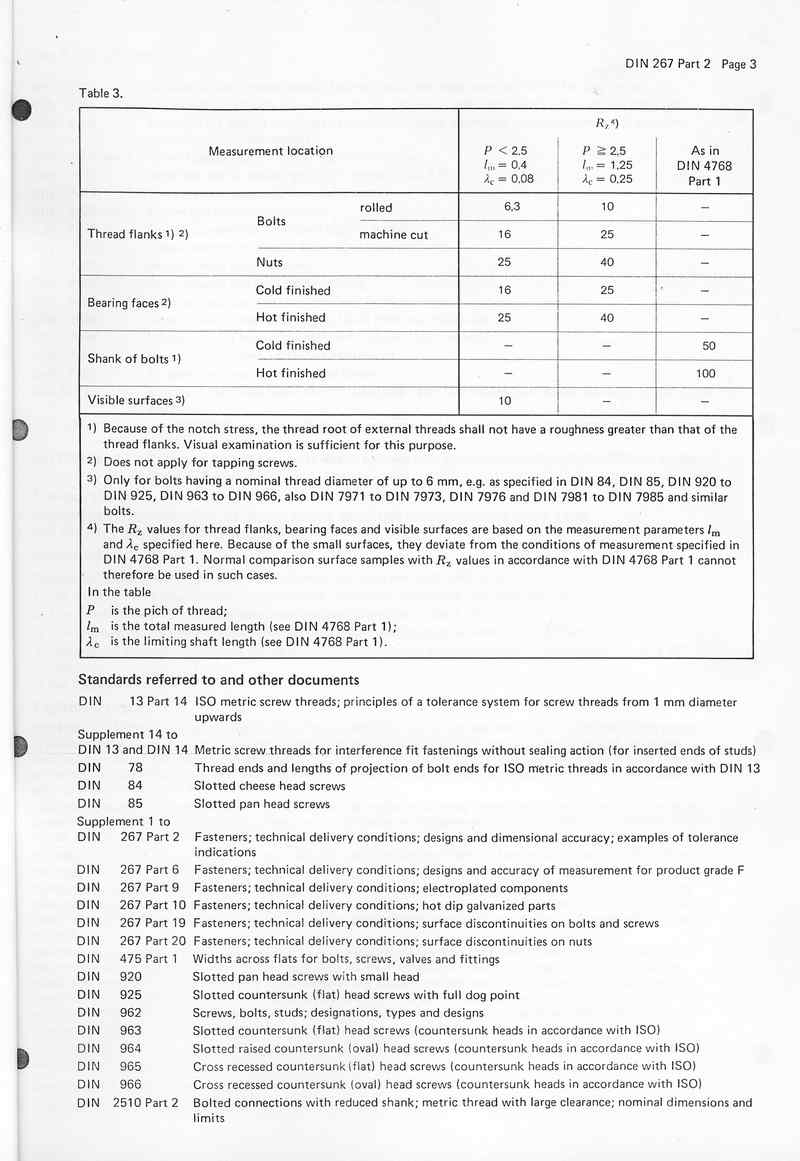
Table 3.
| Measurement location | Rz 4) | ||||
|---|---|---|---|---|---|
| P < 2.5 lm = 0,4 λc = 0,08 |
P ≥ 2,5 lm = 1,25 λc = 0,25 |
As in DIN 4768 Part 1 | |||
| Thread flanks 1) 2) | Bolts | rolled | 6,3 | 10 | — |
| machine cut | 16 | 25 | — | ||
| Nuts | 25 | 40 | — | ||
| Bearing faces 2) | Cold finished | 16 | 25 | — | |
| Hot finished | 25 | 40 | — | ||
| Shank of bolts 1) | Cold finished | — | — | 50 | |
| Hot finished | — | — | 100 | ||
| Visible surfaces 3) | 10 | — | — | ||
1) Because of the notch stress, the thread root of external threads shall not have a roughness greater than that of the thread flanks. Visual examination is sufficient for this purpose.
2) Does not apply for tapping screws.
3) Only for bolts having a nominal thread diameter of up to 6 mm, e.g. as specified in DIN 84, DIN 85, DIN 920 to DIN 925, DIN 963 to DIN 966, also DIN 7971 to DIN 7973, DIN 7976 and DIN 7981 to DIN 7985 and similar bolts.
4) The Rz values for thread flanks, bearing faces and visible surfaces are based on the measurement parameters lm and λc specified here. Because of the small surfaces, they deviate from the conditions of measurement specified in DIN 4768 Part 1. Normal comparison surface samples with Rz values in accordance with DIN 4768 Part 1 cannot therefore be used in such cases.
In the table
P is the pitch of thread;
lm is the total measured length (see DIN 4768 Part 1);
λc is the limiting shaft length (see DIN 4768 Part 1).
Standards referred to and other documents
| DIN 13 Part 14 | ISO metric screw threads; principles of a tolerance system for screw threads from 1 mm diameter upwards |
| Supplement 14 to DIN 13 and DIN 14 | Metric screw threads for interference fit fastenings without sealing action (for inserted ends of studs) |
| DIN 78 | Thread ends and lengths of projection of bolt ends for ISO metric threads in accordance with DIN 13 |
| DIN 84 | Slotted cheese head screws |
| DIN 85 | Slotted pan head screws |
| Supplement 1 to DIN 267 Part 2 | Fasteners; technical delivery conditions; designs and dimensional accuracy; examples of tolerance indications |
| DIN 267 Part 6 | Fasteners; technical delivery conditions; designs and accuracy of measurement for product grade F |
| DIN 267 Part 9 | Fasteners; technical delivery conditions; electroplated components |
| DIN 267 Part 10 | Fasteners; technical delivery conditions; hot dip galvanized parts |
| DIN 267 Part 19 | Fasteners; technical delivery conditions; surface discontinuities on bolts and screws |
| DIN 267 Part 20 | Fasteners; technical delivery conditions; surface discontinuities on nuts |
| DIN 475 Part 1 | Widths across flats for bolts, screws, valves and fittings |
| DIN 920 | Slotted pan head screws with small head |
| DIN 925 | Slotted countersunk (flat) head screws with full dog point |
| DIN 962 | Screws, bolts, studs; designations, types and designs |
| DIN 963 | Slotted countersunk (flat) head screws (countersunk heads in accordance with ISO) |
| DIN 964 | Slotted raised countersunk (oval) head screws (countersunk heads in accordance with ISO) |
| DIN 965 | Cross recessed countersunk (flat) head screws (countersunk heads in accordance with ISO) |
| DIN 966 | Cross recessed countersunk (oval) head screws (countersunk heads in accordance with ISO) |
| DIN 2510 Part 2 | Bolted connections with reduced shank; metric thread with large clearance; nominal dimensions and limits |
3
DIN 267 Part 2
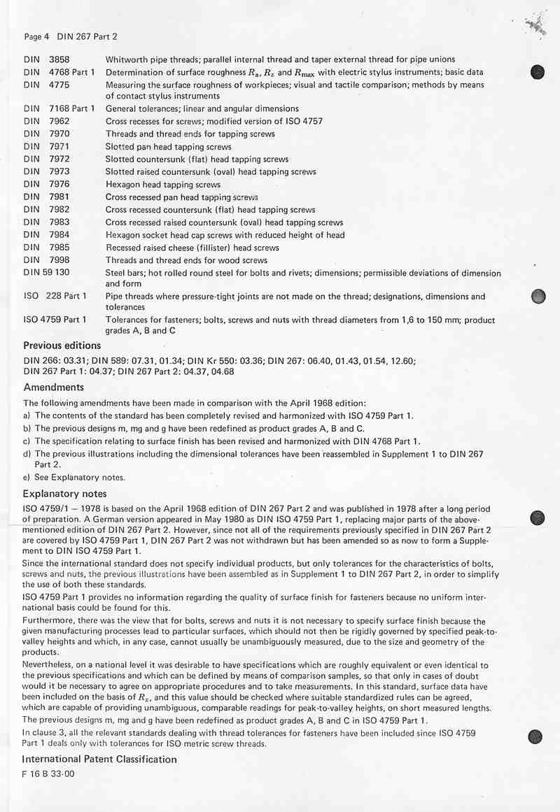
| DIN 3858 | Whitworth pipe threads; parallel internal thread and taper external thread for pipe unions |
| DIN 4768 Part 1 | Determination of surface roughness Ra, Rz and Rmax with electric stylus instruments; basic data |
| DIN 4775 | Measuring the surface roughness of workpieces; visual and tactile comparison; methods by means of contact stylus instruments |
| DIN 7168 Part 1 | General tolerances; linear and angular dimensions |
| DIN 7962 | Cross recesses for screws; modified version of ISO 4757 |
| DIN 7970 | Threads and thread ends for tapping screws |
| DIN 7971 | Slotted pan head tapping screws |
| DIN 7972 | Slotted countersunk (flat) head tapping screws |
| DIN 7973 | Slotted raised countersunk (oval) head tapping screws |
| DIN 7976 | Hexagon head tapping screws |
| DIN 7981 | Cross recessed pan head tapping screws |
| DIN 7982 | Cross recessed countersunk (flat) head tapping screws |
| DIN 7983 | Cross recessed raised countersunk (oval) head tapping screws |
| DIN 7984 | Hexagon socket head cap screws with reduced height of head |
| DIN 7985 | Recessed raised cheese (fillister) head screws |
| DIN 7998 | Threads and thread ends for wood screws |
| DIN 59 130 | Steel bars; hot rolled round steel for bolts and rivets; dimensions; permissible deviations of dimension and form |
| ISO 228 Part 1 | Pipe threads where pressure-tight joints are not made on the thread; designations, dimensions and tolerances |
| ISO 4759 Part 1 | Tolerances for fasteners; bolts, screws and nuts with thread diameters from 1,6 to 150 mm; product grades A, B and C |
Previous editions
DIN 266: 03.31; DIN 589: 07.31, 01.34; DIN Kr 550: 03.36; DIN 267: 06.40, 01.43, 01.54, 12.60; DIN 267 Part 1: 04.37; DIN 267 Part 2: 04.37, 04.68
Amendments
The following amendments have been made in comparison with the April 1968 edition:
a) The contents of the standard has been completely revised and harmonized with ISO 4759 Part 1.
b) The previous designs m, mg and g have been redefined as product grades A, B and C.
c) The specification relating to surface finish has been revised and harmonized with DIN 4768 Part 1.
d) The previous illustrations including the dimensional tolerances have been reassembled in Supplement 1 to DIN 267 Part 2.
e) See Explanatory notes.
Explanatory notes
ISO 4759/1 – 1978 is based on the April 1968 edition of DIN 267 Part 2 and was published in 1978 after a long period of preparation. A German version appeared in May 1980 as DIN ISO 4759 Part 1, replacing major parts of the above-mentioned edition of DIN 267 Part 2. However, since not all of the requirements previously specified in DIN 267 Part 2 are covered by ISO 4759 Part 1, DIN 267 Part 2 was not withdrawn but has been amended so as now to form a Supplement to DIN ISO 4759 Part 1.
Since the international standard does not specify individual products, but only tolerances for the characteristics of bolts, screws and nuts, the previous illustrations have been assembled as in Supplement 1 to DIN 267 Part 2, in order to simplify the use of both these standards.
ISO 4759 Part 1 provides no information regarding the quality of surface finish for fasteners because no uniform international basis could be found for this.
Furthermore, there was the view that for bolts, screws and nuts it is not necessary to specify surface finish because the given manufacturing processes lead to particular surfaces, which should not then be rigidly governed by specified peak-to-valley heights and which, in any case, cannot usually be unambiguously measured, due to the size and geometry of the products.
Nevertheless, on a national level it was desirable to have specifications which are roughly equivalent or even identical to the previous specifications and which can be defined by means of comparison samples, so that only in cases of doubt would it be necessary to agree on appropriate procedures and to take measurements. In this standard, surface data have been included on the basis of Rz, and this value should be checked where suitable standardized rules can be agreed, which are capable of providing unambiguous, comparable readings for peak-to-valley heights, on short measured lengths.
The previous designs m, mg and g have been redefined as product grades A, B and C in ISO 4759 Part 1.
In clause 3, all the relevant standards dealing with thread tolerances for fasteners have been included since ISO 4759 Part 1 deals only with tolerances for ISO metric screw threads.
International Patent Classification
F 16 B 33-00
4
DIN 267 Teil 13
| AD-Merkblatt W 2 | Austenitische Stähle |
| AD-Merkblatt W 7 | Werkstoffe für Druckbehälter; Schrauben und Muttern aus ferritischen Stählen |
| AD-Merkblatt W 10 | Werkstoffe für tiefe Temperaturen |
| TRD 106 | Technische Regeln für Dampfkessel; Schrauben und Muttern aus Stahl |
| VdTÜV WB 435/3¹) | Warmfester austenitischer Walz- und Schmiedestahl X 5 NiCrTi 26 15 Werkstoff Nr.1.4980 |
| VdTÜV WB 490¹) | Schrauben und Muttern aus dem warmfesten Stahl 35 B 2; Werkstoff Nr.1.5511 |
Frühere Ausgaben
DIN 267 Teil 13: 07.68, 03.80
Änderungen
Gegenüber der Ausgabe März 1980 wurden folgende Änderungen vorgenommen:
a) Norm wurde in DIN 267 Teil 13 und DIN 267 Teil 29 aufgeteilt.
b) Titel und Anwendungsbereich wurden geändert.
c) Die Abschnitte 3, 4, 5, 6 und 7 über Gewinde, Produktklassen, Rauhtiefen und Toleranzen wurden in die Norm DIN 267 Teil 29 übernommen.
d) In der Tabelle 1 wurden die Werkstoffe mit den Normen DIN 17 280 und DIN 17440 abgestimmt. Die Werkstoffe X 12 CrNi 18 9 (1.6900) und X 10 CrNiTi 18 10 (1.6903) wurden gestrichen.
e) Die Bedeutung des Zusatzes „-2“ zur Festigkeitsklasse wurde erweitert.
f) In den Tabellen 2 und 3 ist der Zusatz „-2“ zu der Festigkeitsklasse 5.6 entfallen (Fehlerberichtigung), die Festigkeitsklasse 4.6-2 wurde gestrichen.
g) Die Warmstreckgrenzen für die Festigkeitsklasse 8.8 wurden in der Tabelle 3 als allgemeingültig ausgewiesen. Der bisherige Hinweis auf „Anhaltswerte“ wurde gestrichen.
h) In der Tabelle 4 wurde der Werkstoff Cq 35 durch 35 B 2 ersetzt.
i) In der Tabelle 4 „Werkstoffe“ wurde für den Werkstoff C 35 zusätzlich der Zustand „vergütet (V)“ festgelegt.
j) Der Anhang A wurde gestrichen.
k) Der Abschnitt Anwendungsbeispiele wurde gestrichen.
l) Der Inhalt der Norm wurde redaktionell überarbeitet.
Erläuterungen
Die Aufteilung der früheren Norm DIN 267 Teil 13 in zwei getrennte Normen wurde aus folgenden Gründen vorgenommen:
1) Mechanische Eigenschaften (Festigkeitsklassen, Werkstoffe) und Produktklassen (Toleranzen) für mechanische Verbindungselemente werden üblicherweise in getrennten Normen festgelegt und bei Bestellung der Produkte getrennt angegeben.
2) Ein fester Zusammenhang zwischen den mechanischen Eigenschaften nach DIN 267 Teil 13 und Toleranzen nach DIN 267 Teil 29 besteht nicht. Es muß z. B. möglich sein, Verbindungselemente für den Einsatz bei tiefen Temperaturen aus Werkstoffen nach DIN 267 Teil 13 zu bestellen, ohne daß zugleich eine der Toleranzklassen nach DIN 267 Teil 29 gilt.
Durch Querverweise in beiden Normen soll ihre Anwendung insbesondere auch mit Rücksicht auf bestehende Unterlagen erleichtert werden.
Der Zusatz „-2“ bei der Festigkeitsklasse 5 für Muttern bedeutet nunmehr, daß neben Thomasstahl auch Automatenstahl nicht zulässig ist. Diese Festlegung ist nach Meinung der Experten für die im Anwendungsbereich der Norm angegebenen Einsatzgebiete der Verbindungselemente unverzichtbar. Das Verbot von Automatenstahl bedeutet natürlich nicht, daß solche Muttern nicht spanend hergestellt werden dürfen.
Im Text der Norm wird auf die Norm DIN 267 Teil 29 verwiesen. Der Entwurf zu dieser Norm lief unter der Nummer DIN 2510 Teil 9. Die Nummernänderung war aus formalen Gründen (Gleichheit der Gruppentitel) notwendig.
Internationale Patentklassifikation
F 16 B 035/00
F 16 B 037/00
F 16 B 033/00
F 16 B 017/00
1) Zu beziehen bei: Verlag TÜV Rheinland GmbH, Postfach 10 17 50, 50672 Köln.
5
Tabelle 3 (fortgesetzt)
| Lehren | Außendurchmesser | Flankendurchmesser | Kerndurchmesser | Steigung | Teil-Flankenwinkel | Lehrenlänge (Richtwerte) | ||||||
|---|---|---|---|---|---|---|---|---|---|---|---|---|
| Soll-maße mm |
Grenz-ab-maße µm |
Soll-maße mm |
Grenz-ab-maße µm |
Zul. Abnutzung µm |
Soll-maße mm |
Grenz-ab-maße µm |
Tpa µm |
Tα/2 min |
mm | |||
| Außen-gewinde | Gewinde-Gutlehring | Mindestmaß: 48,254 | 42,225 | ±21 | +48 0 |
37,254 | ±21 | ±7 | ±7 | 56 | ||
| Gewinde-Einstelllehre | Gut | 47,254 | ±26 | 42,190 | ±11 | – | Höchstmaß: 36,254 | ±6 | ±7 | 45 | ||
| Ausschuss | 46,779 | ±26 | 41,747 | ±11 | – | Höchstmaße: 35,779 | ±6 | ±7 | 45 | |||
| Gewinde-Ausschusslehring | mit Einstich; Mindestmaß: 48,254 | 41,758 | ±21 | +36 0 |
39,758 | ±42 | ±6 | ±9 | 40 | |||
a Die Steigungstoleranz Tp gilt für eine beliebige Anzahl innerhalb der Gewindelänge der Lehre liegender Gänge.
Tabelle 4 — Lehrenmaße für Gewinde der Normenreihe DIN 263 – Tr 40 × 16 P8
| Lehren | Außendurchmesser | Flankendurchmesser | Kerndurchmesser | Steigung | Teil-Flankenwinkel | Lehrenlänge (Richtwerte) | ||||||
|---|---|---|---|---|---|---|---|---|---|---|---|---|
| Soll-maße mm |
Grenz-ab-maße µm |
Soll-maße mm |
Grenz-ab-maße µm |
Zul. Abnutzung µm |
Soll-maße mm |
Grenz-ab-maße µm |
Tpa µm |
Tα/2 min |
mm | |||
| Innengewinde | Gewinde-Gutlehrdorn | 40,035 | ±26 | 36,035 | ±13 | 0 –39 |
Höchstmaß: 31,500 | ±7 | ±8 | 60 | ||
| Gewinde-Ausschusslehrdorn | 38,013 | ±26 | 36,413 | ±13 | 0 –28 |
mit Einstich; Höchstmaß: 31,500 | ±6 | ±10 | 45 | |||
| Außen-gewinde | Gewinde-Gutlehring | Mindestmaß: 40,500 | 35,225 | ±21 | +48 0 |
33,000 | ±21 | ±7 | ±8 | 60 | ||
| Gewinde-Einstelllehre | Gut | 40,000 | ±26 | 35,190 | ±11 | – | Höchstmaß: 31,500 | ±6 | ±8 | 50 | ||
| Ausschuss | 39,600 | ±26 | 34,822 | ±11 | – | Höchstmaße: 31,100 | ±6 | ±8 | 50 | |||
| Gewinde-Ausschusslehring | mit Einstich; Mindestmaß: 40,500 | 34,833 | ±21 | +36 0 |
33,233 | ±42 | ±6 | ±10 | 45 | |||
a Die Steigungstoleranz Tp gilt für eine beliebige Anzahl innerhalb der Gewindelänge der Lehre liegender Gänge.
6
预览内容由文件识别整理,表格、公式及文字请以原始文件为准。
原文图片预览
PAGE IMAGES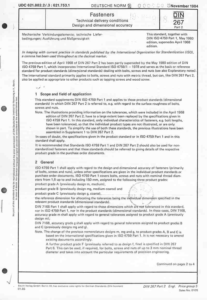
下载标准文件
DIN 267-2-1984.11(1)
英语 · PDF · 6 页 · 15.89 MB