DIN 267-27(1)
紧固件 涂胶钢制螺钉、螺栓和双头螺栓 技术交货条件
DIN 267-27(1)
Fasteners Adhesive-coated steel screws, bolts and studs Technical delivery conditions
标准信息
STANDARD INFORMATION- 标准编号
- DIN 267-27(1)
- 所属分类
- DIN 德国标准
- 发布机构
- DIN
- 版本年份
- 1997
- 文件语言
- 英语
- 文件格式
- 文件页数
- 6 页
- 文件大小
- 15.54 MB
中文名称为参考译名,文件语言以原文为准。
· 更新:
标准简介
OVERVIEW中文简介
该标准规定了M5至M39规格、带有ISO公制螺纹的涂胶钢制螺钉、螺栓和双头螺栓的技术交货条件。它详细定义了微胶囊粘合剂涂层的要求,包括拧紧扭矩、脱扣扭矩和松动扭矩的具体数值及测试方法,以确保紧固件在受力状态下具有防松功能。
English summary
This standard specifies the technical delivery conditions for M5 to M39 adhesive-coated steel screws, bolts, and studs with ISO metric threads. It defines requirements for microencapsulated adhesive coatings, including specific values for tightening, breakaway, and loosening torques, as well as testing methods to ensure anti-loosening performance under stress.
以上为根据文件整理的内容简介。
相关标签
标准内容预览
DOCUMENT PREVIEWFasteners
Adhesive-coated steel screws, bolts and studs
Technical delivery conditions
DIN 267
Part 27
Mechanische Verbindungselemente; Schrauben aus Stahl mit klebender Beschichtung; technische Lieferbedingungen
In keeping with current practice in standards published by the International Organization for Standardization (ISO), a comma has been used throughout as the decimal marker.
1 Scope and field of application
This standard specifies technical delivery conditions for M5 to M39 adhesive-coated steel screws, bolts and studs ('bolts', for short) with ISO metric screw thread as specified in ISO 261 and assigned to property classes as specified in ISO 898 Part 1.
2 Concepts
For the purposes of this standard, the following definitions apply.
2.1 Adhesive coating
Adhesive coating is a coating applied on the thread of bolts (over their whole circumference) in the form of microencapsulated adhesive, the bonding properties of which are activated by the process of bolting and which serves to prevent the bolts working loose.
2.2 Screw-in torque
The screw-in torque, MIN, is the torque measured when a bolt is screwed into a test nut.
2.3 Tightening torque
The tightening torque, MA, is the torque required to tighten a bolt to a level of stress as given in table 1.
2.4 Breakaway torque
The breakaway torque, MLB, is the torque measured at the moment when the relative motion between test nut and bolt is detected in both stressed and unstressed assemblies.
2.5 Loosening torque
The loosening torque, MOUT, is the torque measured after the breakaway point when unscrewing adhesive-coated bolts.
3 Dimensions and designation
3.1 Standard coating
Unless otherwise specified, the coating shall cover a zone, measured from the bolt end, of length equal to 1,5d ± 2P for P smaller than 1 and 1,5d ± P for P equal to or greater than 1.
The first two or three turns of thread should be free from coating material to facilitate bolting.
2 or 3 turns of thread left uncoated
d = nominal bolt thread diameter
P = pitch
Figure 1. Length and position of coated zone on bolts with standard coating
3.2 Non-standard coating
If, for design reasons, a different length, lb, or distance from the bolt end, a, of the coated zone is required (see figure 2), both dimensions shall be indicated in the standard designation (cf. subclause 3.3), both dimensions being subject to a tolerance equal to ± 2P for P smaller than 1, and to ± P for P equal to or greater than 1.
lb = length of coated zone
a = distance of coated zone from bolt end
P = pitch
Figure 2. Length and position of coated zone on bolts with non-standard coating
For lengths of engagement exceeding 1d and property classes below 8.8, the coating length is to be specified as a function of the property class to permit disassembly. The correct coating length may be determined by testing, where necessary.
Continued on pages 2 to 4
1
3.3 Designation
Bolts provided with an adhesive coating as specified in this standard shall be identified by inclusion of the symbol MK.
Examples of designation
Designation of an adhesive-coated (MK) M12 hexagon head bolt as specified in DIN 933, of nominal length, l = 80 mm, assigned to property class 8.8:
Bolt DIN 933 – M12 × 80 – 8.8 – MK
Designation of an M12 hexagon head bolt as specified in DIN 933, of nominal length, l = 80 mm, assigned to property class 8.8 and provided with an adhesive coating (MK) 30 mm in length, with a = 10 mm (30 × 10):
Bolt DIN 933 – M12 × 80 – 8.8 – MK 30 × 10
4 Requirements
4.1 General
When bolts are tested in accordance with subclause 5.2, the specifications regarding MLB/MA ratio and MOUT given in table 1 shall be complied with.
4.2 Requirements to be met by bolts when tested under stress
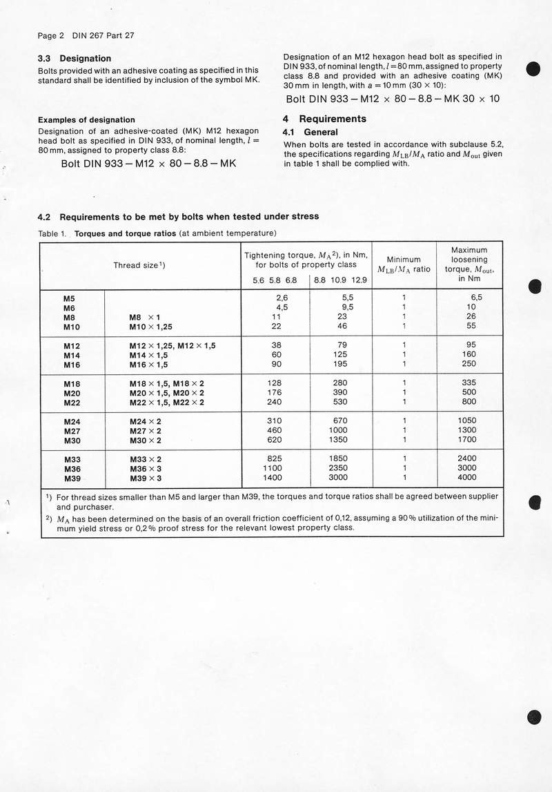
| Thread size1) | Tightening torque, MA2), in Nm, for bolts of property class | Minimum MLB/MA ratio | Maximum loosening torque, MOUT, in Nm | ||
|---|---|---|---|---|---|
| 5.6 5.8 6.8 | 8.8 10.9 12.9 | ||||
| M5 | 2,6 | 5,5 | 1 | 6,5 | |
| M6 | 4,5 | 9,5 | 1 | 10 | |
| M8 | M8 × 1 | 11 | 23 | 1 | 26 |
| M10 | M10 × 1,25 | 22 | 46 | 1 | 55 |
| M12 | M12 × 1,25, M12 × 1,5 | 38 | 79 | 1 | 95 |
| M14 | M14 × 1,5 | 60 | 125 | 1 | 160 |
| M16 | M16 × 1,5 | 90 | 195 | 1 | 250 |
| M18 | M18 × 1,5, M18 × 2 | 128 | 280 | 1 | 335 |
| M20 | M20 × 1,5, M20 × 2 | 176 | 390 | 1 | 500 |
| M22 | M22 × 1,5, M22 × 2 | 240 | 530 | 1 | 800 |
| M24 | M24 × 2 | 310 | 670 | 1 | 1050 |
| M27 | M27 × 2 | 460 | 1000 | 1 | 1300 |
| M30 | M30 × 2 | 620 | 1350 | 1 | 1700 |
| M33 | M33 × 2 | 825 | 1850 | 1 | 2400 |
| M36 | M36 × 3 | 1100 | 2350 | 1 | 3000 |
| M39 | M39 × 3 | 1400 | 3000 | 1 | 4000 |
1) For thread sizes smaller than M5 and larger than M39, the torques and torque ratios shall be agreed between supplier and purchaser.
2) MA has been determined on the basis of an overall friction coefficient of 0,12, assuming a 90 % utilization of the minimum yield stress or 0,2 % proof stress for the relevant lowest property class.
2
4.3 Requirements for bolts when tested not under stress
When bolts are tested in accordance with subclause 5.3, the specifications regarding MLB and Mout given in table 2 shall be complied with.
| Thread size1) | Torques, in Nm | |||
|---|---|---|---|---|
| Min max. | MLB min. | Mout max. | ||
| M5 | M8 × 1 M10 × 1,25 | 1 | 1 | 6,5 |
| M6 | 1,5 | 1,8 | 10 | |
| M8 | 3 | 4 | 26 | |
| M10 | 5,5 | 10 | 55 | |
| M12 | M12 × 1,25, M12 × 1,5 M14 × 1,5 M16 × 1,5 | 7,5 | 16 | 95 |
| M14 | 11 | 22 | 160 | |
| M16 | 14 | 35 | 250 | |
| M18 | M18 × 1,5, M18 × 2 M20 × 1,5, M20 × 2 M22 × 1,5, M22 × 2 | 19 | 40 | 335 |
| M20 | 22 | 45 | 500 | |
| M22 | 30 | 65 | 800 | |
| M24 | M24 × 2 M27 × 2 M30 × 2 | 36 | 90 | 1050 |
| M27 | 42 | 120 | 1300 | |
| M30 | 49 | 165 | 1700 | |
| M33 | M33 × 2 M36 × 3 M39 × 3 | 55 | 210 | 2400 |
| M36 | 60 | 280 | 3000 | |
| M39 | 70 | 330 | 4000 | |
| 1) For thread sizes smaller than M5 and larger than M39, the torques shall be agreed between supplier and purchaser. | ||||
5 Testing
For testing compliance with the requirements specified in tables 1 and 2, bolt/nut assemblies are to be subjected to a test with the assembly under stress (cf. subclause 5.2), this serving as a basis for acceptance.
For routine in-production testing, a second method where the assembly is not subjected to stress is acceptable (cf. subclause 5.3).
5.1 Test equipment
5.1.1 Torquemeter
For torque measurement, a device (e.g. torquemeter), accurate to within 2 % for the upper limit of the given torque range, shall be used. In cases of arbitration, the device shall be chosen so that all values can be read off in the upper half of the measuring range.
5.1.2 Test nut
The test nut shall meet the following requirements.
a) The property class shall at least be equal to that of the bolt.
b) The nut shall have a height equal to 0,8 d to 0,9 d and be countersunk at 120°.
c) The thread shall be produced to 6H tolerance and the thread surface be bright or blackened.
d) The thread of the nut shall be free from oil or grease, and burr.
Test nuts shall be used once only.
5.2 Testing with bolt under stress
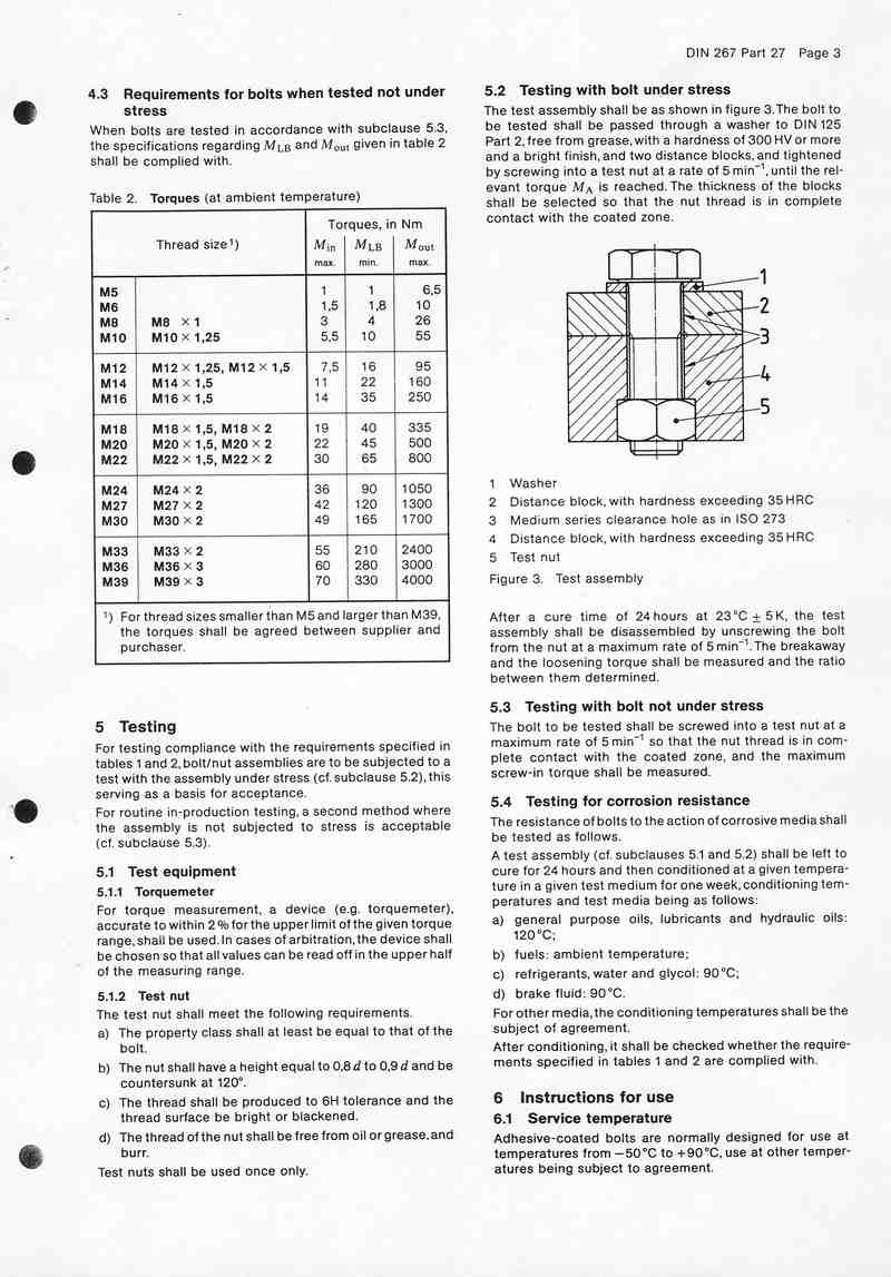
The test assembly shall be as shown in figure 3. The bolt to be tested shall be passed through a washer to DIN 125 Part 2, free from grease, with a hardness of 300 HV or more and a bright finish, and two distance blocks, and tightened by screwing into a test nut at a rate of 5 min-1, until the relevant torque MA is reached. The thickness of the blocks shall be selected so that the nut thread is in complete contact with the coated zone.
1 Washer
2 Distance block, with hardness exceeding 35 HRC
3 Medium series clearance hole as in ISO 273
4 Distance block, with hardness exceeding 35 HRC
5 Test nut
Figure 3. Test assembly
After a cure time of 24 hours at 23 °C ± 5 K, the test assembly shall be disassembled by unscrewing the bolt from the nut at a maximum rate of 5 min-1. The breakaway and the loosening torque shall be measured and the ratio between them determined.
5.3 Testing with bolt not under stress
The bolt to be tested shall be screwed into a test nut at a maximum rate of 5 min-1 so that the nut thread is in complete contact with the coated zone, and the maximum screw-in torque shall be measured.
5.4 Testing for corrosion resistance
The resistance of bolts to the action of corrosive media shall be tested as follows.
A test assembly (cf. subclauses 5.1 and 5.2) shall be left to cure for 24 hours and then conditioned at a given temperature in a given test medium for one week, conditioning temperatures and test media being as follows:
a) general purpose oils, lubricants and hydraulic oils: 120 °C;
b) fuels: ambient temperature;
c) refrigerants, water and glycol: 90 °C;
d) brake fluid: 90 °C.
For other media, the conditioning temperatures shall be the subject of agreement.
After conditioning, it shall be checked whether the requirements specified in tables 1 and 2 are complied with.
6 Instructions for use
6.1 Service temperature
Adhesive-coated bolts are normally designed for use at temperatures from −50 °C to +90 °C, use at other temperatures being subject to agreement.
3
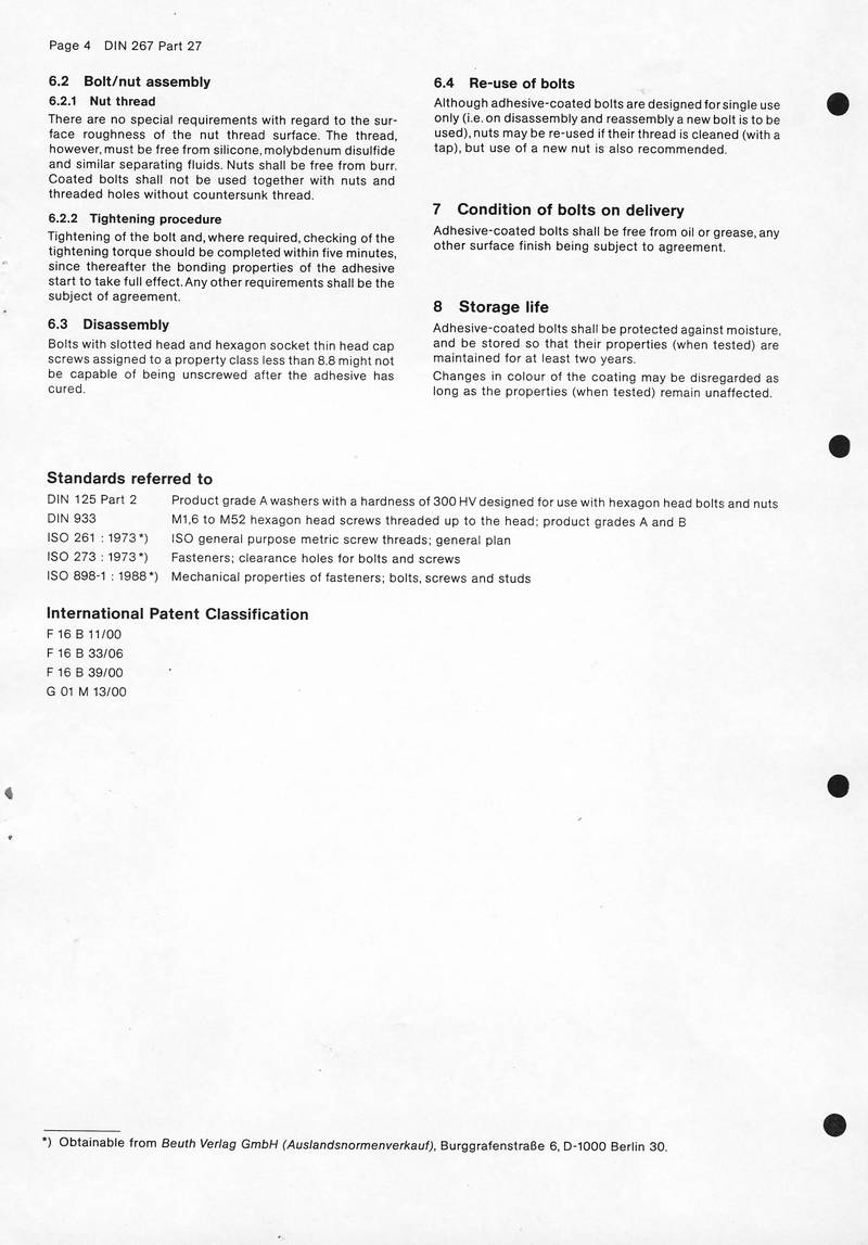
6.2 Bolt/nut assembly
6.2.1 Nut thread
There are no special requirements with regard to the surface roughness of the nut thread surface. The thread, however, must be free from silicone, molybdenum disulfide and similar separating fluids. Nuts shall be free from burr. Coated bolts shall not be used together with nuts and threaded holes without countersunk thread.
6.2.2 Tightening procedure
Tightening of the bolt and, where required, checking of the tightening torque should be completed within five minutes, since thereafter the bonding properties of the adhesive start to take full effect. Any other requirements shall be the subject of agreement.
6.3 Disassembly
Bolts with slotted head and hexagon socket thin head cap screws assigned to a property class less than 8.8 might not be capable of being unscrewed after the adhesive has cured.
6.4 Re-use of bolts
Although adhesive-coated bolts are designed for single use only (i.e. on disassembly and reassembly a new bolt is to be used), nuts may be re-used if their thread is cleaned (with a tap), but use of a new nut is also recommended.
7 Condition of bolts on delivery
Adhesive-coated bolts shall be free from oil or grease, any other surface finish being subject to agreement.
8 Storage life
Adhesive-coated bolts shall be protected against moisture, and be stored so that their properties (when tested) are maintained for at least two years. Changes in colour of the coating may be disregarded as long as the properties (when tested) remain unaffected.
Standards referred to
| DIN 125 Part 2 | Product grade A washers with a hardness of 300 HV designed for use with hexagon head bolts and nuts |
| DIN 933 | M1,6 to M52 hexagon head screws threaded up to the head; product grades A and B |
| ISO 261 : 1973*) | ISO general purpose metric screw threads; general plan |
| ISO 273 : 1973*) | Fasteners; clearance holes for bolts and screws |
| ISO 898-1 : 1988*) | Mechanical properties of fasteners; bolts, screws and studs |
International Patent Classification
F 16 B 11/00
F 16 B 33/06
F 16 B 39/00
G 01 M 13/00
*) Obtainable from Beuth Verlag GmbH (Auslandsnormenverkauf), Burggrafenstraße 6, D-1000 Berlin 30.
4
4.2.6 Spring force test
A spring force test may be carried out in order to assess the springiness of spring washers, this test permitting the residual spring force to be determined.
Place the washer to be tested in a test device and apply the compression load specified in table 7, 8 or 9, the test device being designed to permit as uniform an application of the load as possible. The pressure platen shall have a surface hardness of at least 60 HRC. After two minutes, the load applied to the spring washer shall be slowly and steadily released through a travel of 20 µm, which shall be measured using a precision measuring device (see Explanatory notes).
The residual spring force shall reach the values specified in table 7, 8 or 9, due allowance being made for any deformation of the test device.
The Explanatory notes describe a suitable test device and include examples of spring characteristics.
The residual spring force values represent provisional specifications, with which experience has to be gained. Table 6 summarizes the residual spring forces required for all washer types.
Table 6.
| Type of washer | As specified in | Compression load corresponding to the proof load for property class | Residual spring force after release through travel of 20 µm, as a percentage of the compression load |
|---|---|---|---|
| Spring lock washer | DIN 127 DIN 128, type A DIN 6905 DIN 6913 DIN 7980 |
6.81) | 20% for nominal sizes 4 to 5 30% for nominal sizes 6 to 12 40% for nominal sizes 14 to 20 50% for nominal sizes above 22 |
| Spring washer | DIN 137, type B DIN 6904 |
5.8 | 10% for nominal sizes 4 to 6 15% for nominal sizes 7 to 12 25% for nominal sizes above 12 |
| Conical spring washer2) | DIN 6796 DIN 6908 |
8.8 | 35% for nominal sizes 4 to 5 45% for nominal sizes 6 to 16 60% for nominal sizes 18 to 22 70% for nominal sizes above 22 |
| 1) Spring lock washers which are only intended for bolt/nut assemblies involving fasteners of a property class less than 6.8 are also to be tested at compression loads corresponding to property class 6.8 proof loads. | |||
| 2) The residual spring force values have been determined on conical spring washers complying with DIN 6796. | |||
Table 7. Spring lock washers as specified in DIN 127, DIN 128 (type A), DIN 6905 *), DIN 6913, DIN 7980
| Nominal size | 4 | 5 | 6 | 8 | 10 | 12 | 14 | 16 | 18 |
|---|---|---|---|---|---|---|---|---|---|
| Compression load1), in N | 3050 | 5050 | 7050 | 12 900 | 20 600 | 30 000 | 41 300 | 56 300 | 69 000 |
| Minimum residual spring force, in N | 600 | 1000 | 2100 | 3 900 | 6 200 | 9 000 | 16 500 | 22 500 | 27 600 |
| Nominal size | 20 | 22 | 24 | 27 | 30 | 332) | 36 |
|---|---|---|---|---|---|---|---|
| Compression load1), in N | 88 000 | 110 000 | 127 000 | 167 000 | 204 000 | 255 000 | 298 000 |
| Minimum residual spring force, in N | 35 200 | 55 000 | 63 000 | 83 000 | 102 000 | 127 000 | 149 000 |
| 1) Corresponding to property class 6.8. | |||||||
| 2) Nominal size not included in DIN 127 and DIN 128 (type A). | |||||||
*) As a deviation from the specifications of the product standards for washers and lock washers for screw assemblies, the bolt thread size instead of the washer or lock washer inside diameter shall be used as the relevant nominal size.
5
Table 8. Spring washers as specified in DIN 137 (type B), DIN 6904 *)
| Nominal size | 4 | 5 | 6 | 7 | 8 | 10 | 12 | 14 | 16 |
|---|---|---|---|---|---|---|---|---|---|
| Compression load 1), in N | 2700 | 4000 | 6150 | 9000 | 11 300 | 18 000 | 26 200 | 36 100 | 49 200 |
| Minimum residual spring force, in N | 270 | 400 | 615 | 1350 | 1 700 | 2 700 | 3 900 | 9 000 | 12 300 |
| Nominal size | 18 | 20 | 22 | 24 | 27 | 30 | 33 | 36 |
|---|---|---|---|---|---|---|---|---|
| Compression load 1), in N | 60 000 | 78 000 | 97 000 | 111 000 | 146 000 | 178 000 | 223 000 | 261 000 |
| Minimum residual spring force, in N | 15 000 | 19 500 | 24 200 | 27 800 | 36 500 | 44 500 | 55 700 | 65 200 |
| 1) Corresponding to property class 5.8. | ||||||||
Table 9. Conical spring washers as specified in DIN 6796, DIN 6908 *)
| Nominal size | 4 | 5 | 6 | 7 | 8 | 10 | 12 | 14 | 16 |
|---|---|---|---|---|---|---|---|---|---|
| Compression load 1), in N | 4050 | 6700 | 9400 | 13 700 | 17 200 | 27 500 | 40 000 | 55 000 | 75 000 |
| Minimum residual spring force, in N | 1400 | 2300 | 4200 | 6 200 | 7 700 | 12 400 | 18 000 | 25 000 | 34 000 |
| Nominal size | 18 | 20 | 22 | 24 | 27 | 30 |
|---|---|---|---|---|---|---|
| Compression load 1), in N | 95 000 | 122 000 | 152 000 | 175 000 | 230 000 | 280 000 |
| Minimum residual spring force, in N | 57 000 | 73 000 | 91 000 | 122 000 | 161 000 | 196 000 |
| 1) Corresponding to property class 8.8. | ||||||
5 Form of supply
Steel spring washers shall be packed to give adequate protection against mechanical damage during transport. The packages shall be marked with the standard designation specified in the relevant product standard, e.g.:
DIN 127 – A 8 – FSt
The number of units in the package and the manufacturer's symbol shall also be stated on the package.
*) As a deviation from the specifications of the product standards for washers and lock washers for screw assemblies, the bolt thread size instead of the washer or lock washer inside diameter shall be used as the relevant nominal size.
6
预览内容由文件识别整理,表格、公式及文字请以原始文件为准。
原文图片预览
PAGE IMAGES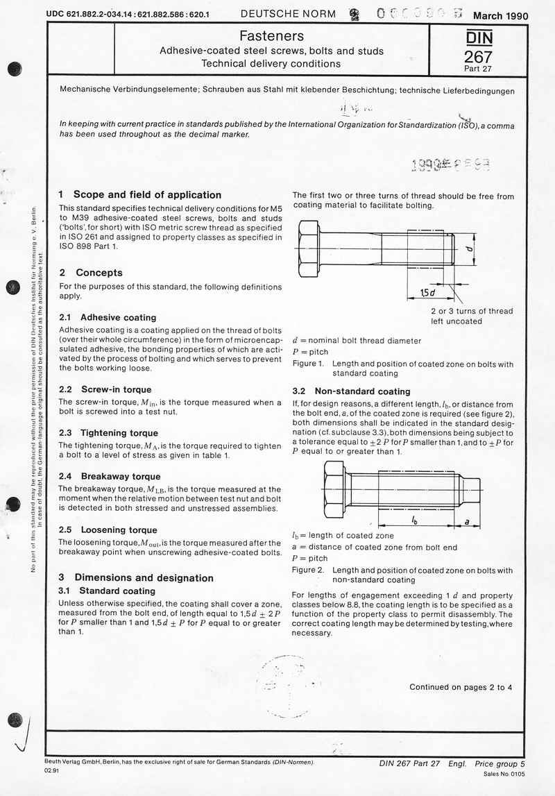
下载标准文件
DIN 267-27(1)
英语 · PDF · 6 页 · 15.54 MB