DIN 267-10(1)
紧固件 技术交货条件 热镀锌件
DIN 267-10(1)
Fasteners Technical delivery conditions Hot-dip galvanized parts
标准信息
STANDARD INFORMATION- 标准编号
- DIN 267-10(1)
- 所属分类
- DIN 德国标准
- 发布机构
- DIN
- 版本年份
- 1977
- 文件语言
- 英语
- 文件格式
- 文件页数
- 6 页
- 文件大小
- 20.21 MB
中文名称为参考译名,文件语言以原文为准。
· 更新:
标准简介
OVERVIEW中文简介
该标准规定了M6至M36粗牙螺纹紧固件(主要是螺栓、螺钉和螺母)的热镀锌技术交货条件。它详细规定了涂层厚度要求、螺纹极限尺寸、最小破坏载荷及证明载荷,适用于性能等级最高为10.9级的螺栓和10级的螺母,同时也涵盖平垫圈和锁紧垫圈等附件。
English summary
This standard specifies the technical delivery conditions for hot-dip galvanized fasteners (mainly screws, bolts, and nuts) with M6 to M36 coarse threads. It details requirements for coating thickness, thread limit dimensions, minimum failure loads, and proof loads for property classes up to 10.9 for bolts and 10 for nuts, also covering accessories like plain and lock washers.
以上为根据文件整理的内容简介。
相关标签
标准内容预览
DOCUMENT PREVIEWFasteners Technical delivery conditions Hot-dip galvanized parts
Mechanische Verbindungselemente; technische Lieferbedingungen; feuerverzinkte Teile
Supersedes March 1977 edition.
In keeping with current practice in standards published by the International Organization for Standardization (ISO), a comma has been used throughout as the decimal marker.
Dimensions in mm
1 Field of application
This standard specifies the technical delivery conditions for fasteners (mainly screws, bolts and nuts) with an M 6 to M 36 coarse thread and provided with a zinc coating applied by hot-dip galvanizing, assigned to property classes up to 10.9 for bolts and 10 for nuts.
The minimum coating thicknesses specified in this standard also apply to hot-dip galvanized accessories such as plain washers and lock washers.
2 General
For most applications, the most important characteristic of hot-dip galvanized fasteners is the thickness of the zinc coating, and not its mass per unit area. This standard thus specifies the coating thickness together with the relevant methods of test. Where an order specifies the mass per unit area, a 100 μm coating thickness may be taken as being equivalent to 700 g/m².
As the fundamental deviations of ISO metric bolt threads produced to tolerance class 6g are not large enough to permit a coating to be applied to the minimum thickness specified in clause 4 without impairing the thread function, one of the two following methods shall be used to ensure that the bolt/nut assembly continues to function properly after hot-dip galvanizing.
a) The bolt thread shall be produced to tolerance position a as specified in DIN 13 Part 15 to give fundamental deviations as specified in table 1 and an actual thread profile corresponding to tolerance class 8 (for product grade C) or tolerance class 6 (for product grade A) before hot-dip galvanizing. After coating, the thread profile shall not at any point transgress the maximum material limit for position h (zero line).
b) The nut shall be produced to the deviation required for the zinc coating process so that the bolt thread may transgress the zero line after coating, this procedure being permissible if bolt and nut are supplied as a set.
The bolt thread shall not be recut after galvanizing. The minimum dimensions of a hot-dip galvanized thread are to be calculated from the minimum dimensions prior to coating, plus the minimum coating thickness (see table 1).
The thread of nuts shall not be hot-dip galvanized, but cut into the blank after coating.
The limit deviations specified in ISO 4759 Part 1 apply to the fastener before galvanizing. Coating shall not impair the ease with which components may be assembled.
Any greyness of hot-dip galvanized coatings is inherent to the material and thus not an indication of inferior quality of corrosion protection.
See DIN 50 976 for requirements relating to hot-dip galvanized coatings on finished ferrous products.
ISO 898 Parts 1 and 2 or DIN 267 Part 4 shall apply for the assessment of the mechanical properties of zinc-coated fasteners. However, as a departure from those standards, lower failure loads and proof loads have been specified taking into account the relatively large fundamental deviations (associated with tolerance position a) and/or the reduced overlap of the bolt and nut threads (see tables 3 and 4).
3 Designation
Hot-dip galvanized fasteners shall be designated as specified in the relevant dimensional standards, additionally using symbol tZn as specified in DIN 50 976, which indicates that the coating thickness is as given in table 1.
Example of designation:
Designation of an M 12 X 50 hexagon head bolt as specified in DIN 601, assigned to property class 4.6, with zinc coating applied by hot-dip galvanizing (tZn):
Hexagon head bolt
DIN 601 — M 12 X 50 — 4.6 — tZn
| Thread size (coarse thread) | Pitch, P | Fundamental deviation, A0, in μm | Minimum coating thickness at measuring point, in μm |
|---|---|---|---|
| M 6 | 1 | − 290 | 40 |
| M 8 | 1,25 | − 295 | 40 |
| M 10 | 1,5 | − 300 | 40 |
| M 12 | 1,75 | − 310 | 40 |
| M 14; M 16 | 2 | − 315 | 40 |
| M 18; M 20; M 22 | 2,5 | − 325 | 40 |
| M 24; M 27 | 3 | − 335 | 40 |
| M 30; M 33 | 3,5 | − 345 | 40 |
| M 36 | 4 | − 355 | 40 |
Continued on pages 2 to 5
1
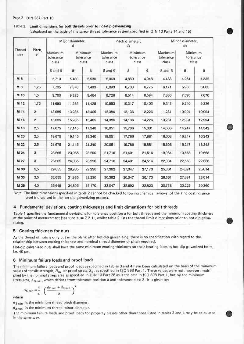
Table 2. Limit dimensions for bolt threads prior to hot-dip galvanizing
(calculated on the basis of the screw thread tolerance system specified in DIN 13 Parts 14 and 15)
| Thread size | Pitch, P | Major diameter, d | Pitch diameter, d2 | Minor diameter, d3 | ||||||
|---|---|---|---|---|---|---|---|---|---|---|
| Maximum tolerance class | Minimum tolerance class | Maximum tolerance class | Minimum tolerance class | Maximum tolerance class | Minimum tolerance class | |||||
| 8 and 6 | 8 | 6 | 8 and 6 | 8 | 6 | 8 and 6 | 8 | 6 | ||
| M 6 | 1 | 5,710 | 5,430 | 5,530 | 5,060 | 4,880 | 4,948 | 4,483 | 4,264 | 4,332 |
| M 8 | 1,25 | 7,705 | 7,370 | 7,493 | 6,893 | 6,703 | 6,775 | 6,171 | 5,933 | 6,005 |
| M 10 | 1,5 | 9,700 | 9,325 | 9,464 | 8,726 | 8,514 | 8,594 | 7,860 | 7,590 | 7,670 |
| M 12 | 1,75 | 11,690 | 11,265 | 11,425 | 10,553 | 10,317 | 10,403 | 9,543 | 9,240 | 9,326 |
| M 14 | 2 | 13,685 | 13,235 | 13,405 | 12,386 | 12,136 | 12,226 | 11,231 | 10,904 | 10,994 |
| M 16 | 2 | 15,685 | 15,235 | 15,405 | 14,386 | 14,136 | 14,226 | 13,231 | 12,904 | 12,994 |
| M 18 | 2,5 | 17,675 | 17,145 | 17,340 | 16,051 | 15,786 | 15,881 | 14,608 | 14,247 | 14,342 |
| M 20 | 2,5 | 19,675 | 19,145 | 19,340 | 18,051 | 17,786 | 17,881 | 16,608 | 16,247 | 16,342 |
| M 22 | 2,5 | 21,675 | 21,145 | 21,340 | 20,051 | 19,786 | 19,881 | 18,608 | 18,247 | 18,342 |
| M 24 | 3 | 23,665 | 23,065 | 23,290 | 21,716 | 21,401 | 21,516 | 19,984 | 19,553 | 19,668 |
| M 27 | 3 | 26,665 | 26,065 | 26,290 | 24,716 | 24,401 | 24,516 | 22,984 | 22,553 | 22,668 |
| M 30 | 3,5 | 29,655 | 28,985 | 29,230 | 27,382 | 27,047 | 27,170 | 25,361 | 24,891 | 25,014 |
| M 33 | 3,5 | 32,655 | 31,985 | 32,230 | 30,382 | 30,047 | 30,170 | 28,361 | 27,891 | 28,014 |
| M 36 | 4,0 | 35,645 | 34,895 | 35,170 | 33,047 | 32,692 | 32,823 | 30,738 | 30,229 | 30,360 |
Note. The limit dimensions specified in table 2 cannot be checked following chemical removal of the zinc coating since steel is dissolved in the hot-dip galvanizing process.
4 Fundamental deviations, coating thicknesses and limit dimensions for bolt threads
Table 1 specifies the fundamental deviations for tolerance position a for bolt threads and the minimum coating thickness at the point of measurement (see subclause 7.2.1), whilst table 2 lists the thread limit dimensions prior to hot-dip galvanizing.
5 Coating thickness for nuts
As the thread of nuts is only cut in the blank after hot-dip galvanizing, there is no specification with regard to the relationship between coating thickness and nominal thread diameter or pitch required.
Hot-dip galvanized nuts shall have the same minimum coating thickness on their bearing faces as hot-dip galvanized bolts, i.e. 40 μm.
6 Minimum failure loads and proof loads
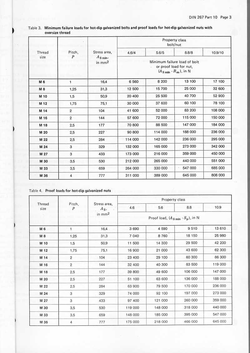
The minimum failure loads and proof loads as specified in tables 3 and 4 have been calculated on the basis of the minimum values of tensile strength, Rm, or proof stress, Sp, as specified in ISO 898 Part 1. These values were not, however, multiplied by the nominal stress area as specified in DIN 13 Part 28 as is the case in ISO 898 Part 1, but by the minimum stress area, AS min, which derives from tolerance position a and tolerance class 8. It is given by:
AS min = π/4 · ((d2 min + d3 min)/2)2
where
d2 min is the minimum thread pitch diameter;
d3 min is the minimum thread minor diameter.
The minimum failure loads and proof loads for property classes other than those listed in tables 3 and 4 may be calculated in the same way.
2
Table 3. Minimum failure loads for hot-dip galvanized bolts and proof loads for hot-dip galvanized nuts with oversize thread
| Thread size | Pitch, P | Stress area, AS min, in mm2 | Property class bolt/nut | |||
|---|---|---|---|---|---|---|
| 4.6/4 | 5.6/5 | 8.8/8 | 10.9/10 | |||
| Minimum failure load of bolt or proof load for nut, (AS min · Rm), in N | ||||||
| M 6 | 1 | 16,4 | 6 560 | 8 200 | 13 100 | 17 100 |
| M 8 | 1,25 | 31,3 | 12 500 | 15 700 | 25 000 | 32 600 |
| M 10 | 1,5 | 50,9 | 20 400 | 25 500 | 40 700 | 52 900 |
| M 12 | 1,75 | 75,1 | 30 000 | 37 600 | 60 100 | 78 100 |
| M 14 | 2 | 104 | 41 600 | 52 000 | 83 200 | 108 000 |
| M 16 | 2 | 144 | 57 600 | 72 000 | 115 000 | 150 000 |
| M 18 | 2,5 | 177 | 70 800 | 88 500 | 147 000 | 184 000 |
| M 20 | 2,5 | 227 | 90 800 | 114 000 | 188 000 | 236 000 |
| M 22 | 2,5 | 284 | 114 000 | 142 000 | 236 000 | 295 000 |
| M 24 | 3 | 329 | 132 000 | 165 000 | 273 000 | 342 000 |
| M 27 | 3 | 433 | 173 000 | 216 000 | 359 000 | 450 000 |
| M 30 | 3,5 | 530 | 212 000 | 265 000 | 440 000 | 551 000 |
| M 33 | 3,5 | 659 | 264 000 | 330 000 | 547 000 | 685 000 |
| M 36 | 4 | 777 | 311 000 | 389 000 | 645 000 | 808 000 |
Table 4. Proof loads for hot-dip galvanized nuts
| Thread size | Pitch, P | Stress area, AS, in mm2 | Property class | |||
|---|---|---|---|---|---|---|
| 4.6 | 5.6 | 8.8 | 10.9 | |||
| Proof load, (AS min · Sp), in N | ||||||
| M 6 | 1 | 16,4 | 3 690 | 4 590 | 9 510 | 13 610 |
| M 8 | 1,25 | 31,3 | 7 040 | 8 760 | 18 150 | 25 980 |
| M 10 | 1,5 | 50,9 | 11 500 | 14 300 | 29 500 | 42 200 |
| M 12 | 1,75 | 75,1 | 16 900 | 21 000 | 43 600 | 62 300 |
| M 14 | 2 | 104 | 23 400 | 29 100 | 60 300 | 86 300 |
| M 16 | 2 | 144 | 32 400 | 40 300 | 83 500 | 119 000 |
| M 18 | 2,5 | 177 | 39 800 | 49 600 | 106 000 | 147 000 |
| M 20 | 2,5 | 227 | 51 100 | 63 600 | 136 000 | 188 000 |
| M 22 | 2,5 | 284 | 63 900 | 79 500 | 170 000 | 236 000 |
| M 24 | 3 | 329 | 74 000 | 92 100 | 197 000 | 273 000 |
| M 27 | 3 | 433 | 97 400 | 121 000 | 260 000 | 359 000 |
| M 30 | 3,5 | 530 | 119 000 | 148 000 | 318 000 | 440 000 |
| M 33 | 3,5 | 659 | 148 000 | 185 000 | 395 000 | 547 000 |
| M 36 | 4 | 777 | 175 000 | 218 000 | 466 000 | 645 000 |
3
7 Testing
DIN 267 Part 5 shall apply for the acceptance inspection of hot-dip galvanized fasteners.
7.1 Proof load test and determination of failure load
The proof load test and the determination of the failure load for bolts shall be carried out as described in ISO 898 Part 1 and the proof load test on nuts with oversize thread, as specified in DIN 267 Part 4. Although, given the special thread tolerances applying here, failure of the bolt during tensile is acceptable as a result of thread stripping, the minimum failure loads specified in table 3 shall still be achieved.
7.2 Determination of coating thickness
7.2.1 Measuring points
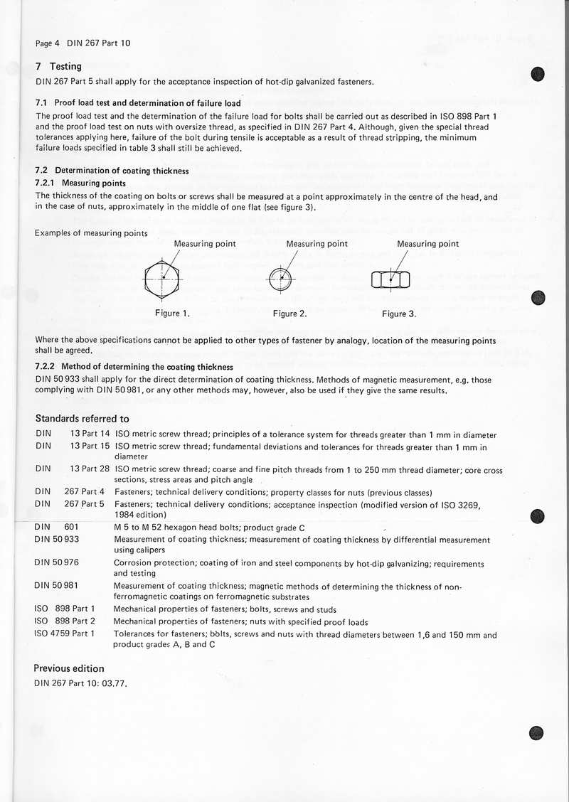
The thickness of the coating on bolts or screws shall be measured at a point approximately in the centre of the head, and in the case of nuts, approximately in the middle of one flat (see figure 3).
Examples of measuring points
Figure 1.
Figure 2.
Figure 3.
Where the above specifications cannot be applied to other types of fastener by analogy, location of the measuring points shall be agreed.
7.2.2 Method of determining the coating thickness
DIN 50 933 shall apply for the direct determination of coating thickness. Methods of magnetic measurement, e.g. those complying with DIN 50 981, or any other methods may, however, also be used if they give the same results.
Standards referred to
| DIN 13 Part 14 | ISO metric screw thread; principles of a tolerance system for threads greater than 1 mm in diameter |
| DIN 13 Part 15 | ISO metric screw thread; fundamental deviations and tolerances for threads greater than 1 mm in diameter |
| DIN 13 Part 28 | ISO metric screw thread; coarse and fine pitch threads from 1 to 250 mm thread diameter; core cross sections, stress areas and pitch angle |
| DIN 267 Part 4 | Fasteners; technical delivery conditions; property classes for nuts (previous classes) |
| DIN 267 Part 5 | Fasteners; technical delivery conditions; acceptance inspection (modified version of ISO 3269, 1984 edition) |
| DIN 601 | M 5 to M 52 hexagon head bolts; product grade C |
| DIN 50 933 | Measurement of coating thickness; measurement of coating thickness by differential measurement using calipers |
| DIN 50 976 | Corrosion protection; coating of iron and steel components by hot-dip galvanizing; requirements and testing |
| DIN 50 981 | Measurement of coating thickness; magnetic methods of determining the thickness of non-ferromagnetic coatings on ferromagnetic substrates |
| ISO 898 Part 1 | Mechanical properties of fasteners; bolts, screws and studs |
| ISO 898 Part 2 | Mechanical properties of fasteners; nuts with specified proof loads |
| ISO 4759 Part 1 | Tolerances for fasteners; bolts, screws and nuts with thread diameters between 1,6 and 150 mm and product grades A, B and C |
Previous edition
DIN 267 Part 10: 03.77.
4
Amendments
The following amendments have been made to the March 1977 edition.
a) Values for the bolt thread minor diameter have been corrected.
b) Minimum failure loads and proof loads have been specified taking into consideration the larger fundamental deviations for hot-dip galvanized bolts produced to a modified tolerance position or for nuts with oversize thread.
c) The standard has been editorially revised.
Explanatory notes
In comparison with the March 1977 edition of this standard, this edition includes minimum failure loads and proof loads for bolts and nuts. These loads are smaller than the values specified in ISO 898 Part 1 or DIN 267 Part 4. This is intended to take account of the increased fundamental deviations (derived from tolerance position a) specified for hot-dip galvanized bolts and screws, the effective stress area here being markedly smaller than the nominal stress area, and the reduced overlap of the bolt and nut threads.
The scope of the standard has been limited to M 6 to M 36 fasteners with coarse thread as, owing to lack of experience in hot-dip galvanizing of bolts larger than size M 36, standard specifications cannot as yet be given and production of fasteners smaller than M 6 (or a pitch smaller than 1 mm) is uneconomical.
Although the specifications given in this standard chiefly apply to bolts, screws and nuts, i.e. to threaded components, they may also be applied to accessories such as plain washers and lock washers.
Despite the fact that there is at present little evidence for hydrogen-induced brittle fracture, such fracture cannot be ruled out in the case of hot-dip galvanized steel bolts having the chemical composition and minimum tempering temperatures specified in ISO 898 Part 1, owing to the pretreatment (pickling) required for components with a tensile strength exceeding 1000 N/mm2. Such fracture, however, can generally be prevented by using suitable materials and by ensuring that pickling is properly carried out.
The specification given in subclause 7.2.2, that other methods of measurement should give the same results does not only mean the same absolute (or mean) values when these test methods are used, but also that these other, unspecified, methods involve the same uncertainty of measurement and the same variability as the methods specified in DIN 50 933. This permits other methods of measurement to be applied without additional inaccuracies or variations in results being introduced.
International Patent Classification
C 23 C 2/06
F 16 B 33/00
5
Tabelle 3 (fortgesetzt)
| Lehren | Außendurchmesser | Flankendurchmesser | Kerndurchmesser | Steigung | Teil-Flankenwinkel | Lehrenlänge (Richtwerte) | ||||||
|---|---|---|---|---|---|---|---|---|---|---|---|---|
| Sollmaße mm |
Grenzabmaße µm |
Sollmaße mm |
Grenzabmaße µm |
Zul. Abnutzung µm |
Sollmaße mm |
Grenzabmaße µm |
Tpa µm |
Tα/2 min |
mm | |||
| Außengewinde | Gewinde-Gutlehring | Mindestmaß: 48,254 | 42,225 | ±21 | +48 0 |
37,254 | ±21 | ±7 | ±7 | 56 | ||
| Gewinde-Einstelllehre | Gut | 47,254 | ±26 | 42,190 | ±11 | – | Höchstmaß: 36,254 | ±6 | ±7 | 45 | ||
| Ausschuss | 46,779 | ±26 | 41,747 | ±11 | – | Höchstmaße: 35,779 | ±6 | ±7 | 45 | |||
| Gewinde-Ausschusslehring | mit Einstich; Mindestmaß: 48,254 | 41,758 | ±21 | +36 0 |
39,758 | ±42 | ±6 | ±9 | 40 | |||
a Die Steigungstoleranz Tp gilt für eine beliebige Anzahl innerhalb der Gewindelänge der Lehre liegender Gänge.
Tabelle 4 — Lehrenmaße für Gewinde der Normenreihe DIN 263 – Tr 40 × 16 P8
| Lehren | Außendurchmesser | Flankendurchmesser | Kerndurchmesser | Steigung | Teil-Flankenwinkel | Lehrenlänge (Richtwerte) | ||||||
|---|---|---|---|---|---|---|---|---|---|---|---|---|
| Sollmaße mm |
Grenzabmaße µm |
Sollmaße mm |
Grenzabmaße µm |
Zul. Abnutzung µm |
Sollmaße mm |
Grenzabmaße µm |
Tpa µm |
Tα/2 min |
mm | |||
| Innengewinde | Gewinde-Gutlehrdorn | 40,035 | ±26 | 36,035 | ±13 | 0 –39 |
Höchstmaß: 31,500 | ±7 | ±8 | 60 | ||
| Gewinde-Ausschusslehrdorn | 38,013 | ±26 | 36,413 | ±13 | 0 –28 |
mit Einstich; Höchstmaß: 31,500 | ±6 | ±10 | 45 | |||
| Außengewinde | Gewinde-Gutlehring | Mindestmaß: 40,500 | 35,225 | ±21 | +48 0 |
33,000 | ±21 | ±7 | ±8 | 60 | ||
| Gewinde-Einstelllehre | Gut | 40,000 | ±26 | 35,190 | ±11 | – | Höchstmaß: 31,500 | ±6 | ±8 | 50 | ||
| Ausschuss | 39,600 | ±26 | 34,822 | ±11 | – | Höchstmaße: 31,100 | ±6 | ±8 | 50 | |||
| Gewinde-Ausschusslehring | mit Einstich; Mindestmaß: 40,500 | 34,833 | ±21 | +36 0 |
33,233 | ±42 | ±6 | ±10 | 45 | |||
a Die Steigungstoleranz Tp gilt für eine beliebige Anzahl innerhalb der Gewindelänge der Lehre liegender Gänge.
6
预览内容由文件识别整理,表格、公式及文字请以原始文件为准。
原文图片预览
PAGE IMAGES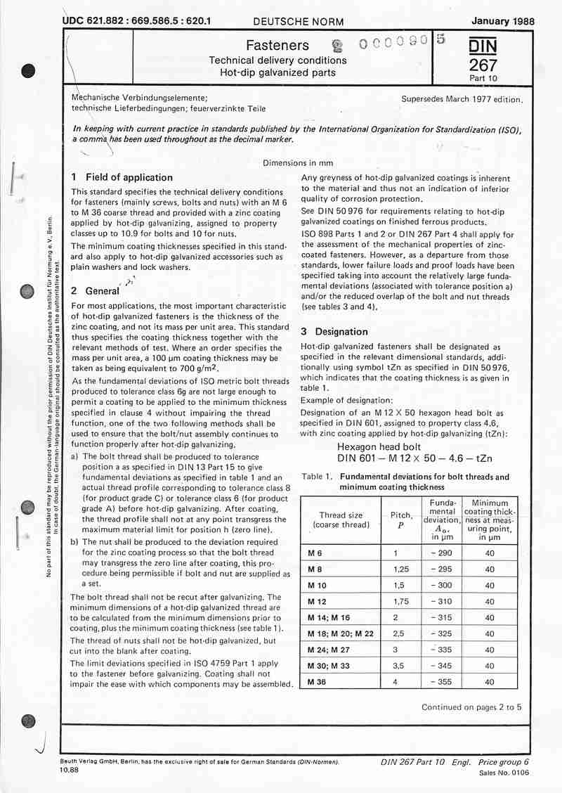
下载标准文件
DIN 267-10(1)
英语 · PDF · 6 页 · 20.21 MB