din-66(1)
ISO 7721通用头型沉头螺钉用沉孔
din-66(1)
Countersinks for countersunk head screws with ISO 7721 common head style
标准信息
STANDARD INFORMATION- 标准编号
- din-66(1)
- 所属分类
- DIN 德国标准
- 发布机构
- DIN
- 版本年份
- 1997
- 文件语言
- 英语
- 文件格式
- 文件页数
- 6 页
- 文件大小
- 12.58 MB
中文名称为参考译名,文件语言以原文为准。
· 更新:
标准简介
OVERVIEW中文简介
该标准规定了适用于ISO 7721通用头型沉头螺钉的中系列沉孔尺寸、公差及表面粗糙度要求。它涵盖了公制螺钉和自攻螺钉对应的沉孔规格,并提供了在工程图纸中的标注方法。
English summary
This standard specifies the dimensions, tolerances, and surface roughness requirements for medium series countersinks designed for ISO 7721 common head style countersunk head screws. It covers specifications for both metric and tapping screws and provides guidelines for indicating these countersinks on engineering drawings.
以上为根据文件整理的内容简介。
相关标签
标准内容预览
DOCUMENT PREVIEWCountersinks for countersunk head screws with ISO 7721 common head style
Senkungen für Senkschrauben mit Einheitköpfen nach ISO 7721
In keeping with current practice in standards published by the International Organization for Standardization (ISO), a comma has been used throughout as the decimal marker.
Dimensions in mm
1 Field of application
This standard specifies countersinks for medium series clearance holes as covered in ISO 273 which are designed to receive countersunk head screws with ISO 7721 common head style, as covered in ISO 1482, 1483, 2009, 2010, 7046, 7047, 7050, and 7051. For countersinks for other types of countersunk head screws, see DIN 74 Part 1.
Continued on pages 2 and 3
Beuth Verlag GmbH, Berlin, has the exclusive right of sale for German Standards (DIN-Normen).
1
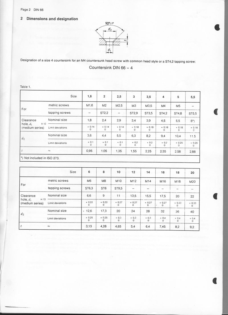
2 Dimensions and designation
Designation of a size 4 countersink for an M4 countersunk head screw with common head style or a ST4,2 tapping screw:
Countersink DIN 66 – 4
Table 1.
| Size | 1,6 | 2 | 2,5 | 3 | 3,5 | 4 | 5 | 5,5 | |
|---|---|---|---|---|---|---|---|---|---|
| For | metric screws | M1,6 | M2 | M2,5 | M3 | M3,5 | M4 | M5 | – |
| tapping screws | – | ST2,2 | – | ST2,9 | ST3,5 | ST4,2 | ST4,8 | ST5,5 | |
| Clearance hole, d1 H 13 (medium series) | Nominal size | 1,8 | 2,4 | 2,9 | 3,4 | 3,9 | 4,5 | 5,5 | 6*) |
| Limit deviations | + 0,14 / 0 | + 0,14 / 0 | + 0,14 / 0 | + 0,18 / 0 | + 0,18 / 0 | + 0,18 / 0 | + 0,18 / 0 | + 0,18 / 0 | |
| d2 | Nominal size | 3,6 | 4,4 | 5,5 | 6,3 | 8,2 | 9,4 | 10,4 | 11,5 |
| Limit deviations | + 0,1 / 0 | + 0,1 / 0 | + 0,1 / 0 | + 0,2 / 0 | + 0,2 / 0 | + 0,2 / 0 | + 0,25 / 0 | + 0,25 / 0 | |
| t | ≈ | 0,95 | 1,05 | 1,35 | 1,55 | 2,25 | 2,55 | 2,58 | 2,88 |
| *) Not included in ISO 273. | |||||||||
| Size | 6 | 8 | 10 | 12 | 14 | 16 | 18 | 20 | |
|---|---|---|---|---|---|---|---|---|---|
| For | metric screws | M6 | M8 | M10 | M12 | M14 | M16 | M18 | M20 |
| tapping screws | ST6,3 | ST8 | ST9,5 | – | – | – | – | – | |
| Clearance hole, d1 H 13 (medium series) | Nominal size | 6,6 | 9 | 11 | 13,5 | 15,5 | 17,5 | 20 | 22 |
| Limit deviations | + 0,22 / 0 | + 0,22 / 0 | + 0,27 / 0 | + 0,27 / 0 | + 0,27 / 0 | + 0,27 / 0 | + 0,33 / 0 | + 0,33 / 0 | |
| d2 | Nominal size | 12,6 | 17,3 | 20 | 24 | 28 | 32 | 36 | 40 |
| Limit deviations | + 0,25 / 0 | + 0,25 / 0 | + 0,3 / 0 | + 0,3 / 0 | + 0,3 / 0 | + 0,4 / 0 | + 0,4 / 0 | + 0,4 / 0 | |
| t | ≈ | 3,13 | 4,28 | 4,65 | 5,4 | 6,4 | 7,45 | 8,2 | 9,2 |
2
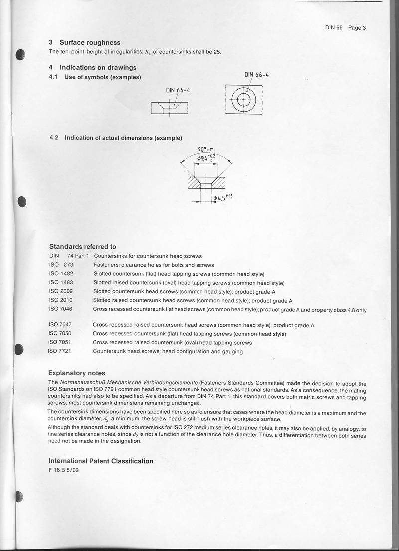
3 Surface roughness
The ten-point-height of irregularities, Rz, of countersinks shall be 25.
4 Indications on drawings
4.1 Use of symbols (examples)
4.2 Indication of actual dimensions (example)
Standards referred to
| DIN 74 Part 1 | Countersinks for countersunk head screws |
| ISO 273 | Fasteners; clearance holes for bolts and screws |
| ISO 1482 | Slotted countersunk (flat) head tapping screws (common head style) |
| ISO 1483 | Slotted raised countersunk (oval) head tapping screws (common head style) |
| ISO 2009 | Slotted countersunk head screws (common head style); product grade A |
| ISO 2010 | Slotted raised countersunk head screws (common head style); product grade A |
| ISO 7046 | Cross recessed countersunk flat head screws (common head style); product grade A and property class 4.8 only |
| ISO 7047 | Cross recessed raised countersunk head screws (common head style); product grade A |
| ISO 7050 | Cross recessed countersunk (flat) head tapping screws (common head style) |
| ISO 7051 | Cross recessed raised countersunk (oval) head tapping screws |
| ISO 7721 | Countersunk head screws; head configuration and gauging |
Explanatory notes
The Normenausschuß Mechanische Verbindungselemente (Fasteners Standards Committee) made the decision to adopt the ISO Standards on ISO 7721 common head style countersunk head screws as national standards. As a consequence, the mating countersinks had also to be specified. As a departure from DIN 74 Part 1, this standard covers both metric screws and tapping screws, most countersink dimensions remaining unchanged.
The countersink dimensions have been specified here so as to ensure that cases where the head diameter is a maximum and the countersink diameter, d2, a minimum, the screw head is still flush with the workpiece surface.
Although the standard deals with countersinks for ISO 272 medium series clearance holes, it may also be applied, by analogy, to fine series clearance holes, since d2 is not a function of the clearance hole diameter. Thus, a differentiation between both series need not be made in the designation.
International Patent Classification
F 16 B 5/02
3
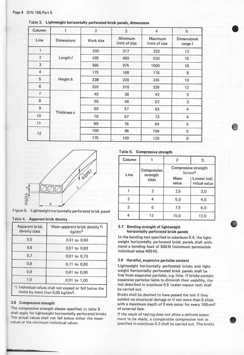
Table 3. Lightweight horizontally perforated brick panels, dimensions
| Column | 1 | 2 | 3 | 4 | 5 |
|---|---|---|---|---|---|
| Line | Dimensions | Work size | Minimum limit of size | Maximum limit of size | Dimensional range t |
| 1 | Length l | 330 | 317 | 333 | 12 |
| 2 | 495 | 480 | 500 | 15 | |
| 3 | 995 | 975 | 1000 | 18 | |
| 4 | Height h | 175 | 168 | 178 | 8 |
| 5 | 238 | 230 | 245 | 10 | |
| 6 | 320 | 310 | 328 | 12 | |
| 7 | Thickness s | 40 | 38 | 42 | 3 |
| 8 | 50 | 48 | 52 | 3 | |
| 9 | 60 | 57 | 63 | 4 | |
| 10 | 70 | 67 | 73 | 4 | |
| 11 | 80 | 76 | 84 | 5 | |
| 12 | 100 | 96 | 104 | 5 | |
| 115 | 100 | 120 | 6 |
Figure 5. Lightweight horizontally perforated brick panel
Table 4. Apparent brick density
| Apparent brick density class | Mean apparent brick density1) kg/dm3 |
|---|---|
| 0,5 | 0,41 to 0,50 |
| 0,6 | 0,51 to 0,60 |
| 0,7 | 0,61 to 0,70 |
| 0,8 | 0,71 to 0,80 |
| 0,9 | 0,81 to 0,90 |
| 1,0 | 0,91 to 1,00 |
| 1) Individual values shall not exceed or fall below the limits by more than 0,05 kg/dm3. | |
3.6 Compressive strength
The compressive strength classes specified in table 5 shall apply for lightweight horizontally perforated bricks. The actual values shall not fall below either the mean values or the minimum individual values.
Table 5. Compressive strength
| Column | 1 | 2 | 3 | |
|---|---|---|---|---|
| Line | Compressive strength class | Mean value | Lowest individual value | |
| 1 | 2 | 2,5 | 2,0 | |
| 2 | 4 | 5,0 | 4,0 | |
| 3 | 6 | 7,5 | 6,0 | |
| 4 | 12 | 15,0 | 12,0 | |
3.7 Bending strength of lightweight horizontally perforated brick panels
In the bending test specified in subclause 6.4, the lightweight horizontally perforated brick panels shall withstand a bending load of 500 N (minimum permissible individual value 400 N).
3.8 Harmful, expansive particles content
Lightweight horizontally perforated bricks and lightweight horizontally perforated brick panels shall be free from expansive particles, e.g. lime. If bricks contain expansive particles liable to diminish their usability, the test described in subclause 6.5 (water vapour test) shall be carried out.
Bricks shall be deemed to have passed the test if they exhibit no structural damage or if not more than 5 chips with a maximum depth of 3 mm occur for every 100 cm2 of external face.
If the result of testing does not allow a definite assessment to be made, a comparative compressive test as specified in subclause 6.3 shall be carried out. The bricks
4
3.9 Content of harmful salts causing efflorescence
Bricks shall be free from harmful salts leading to structural damage in the bricks or plaster. Bricks shall be deemed to have passed the test for harmful salts if the test described in subclause 6.5, carried out on loose bricks, shows that the proportion by mass of magnesium sulfate (MgSO4) does not exceed 0,12 %.
4 Designation
The following symbols shall be used for the various types of brick:
LLz lightweight horizontally perforated brick
LLp lightweight horizontally perforated brick panel
The sequence of elements used when designating lightweight horizontally perforated bricks shall be term, DIN number, type of brick (symbol), compressive strength class, apparent brick density class and format symbol as given in table 6.
Example of designation:
Designation of a lightweight horizontally perforated brick (LLz) of compressive strength class 12, apparent brick density class 0,9, length l = 240 mm, width b = 175 mm and height h = 113 mm (3 DF):
Brick DIN 105 — LLz 12 — 0,9 — 3 DF
The sequence of elements used when designating lightweight horizontally perforated brick panels shall be DIN number, type of brick (symbol), apparent brick density class and format symbol as given in table 7.
Example of designation:
Designation of a lightweight horizontally perforated brick panel (LLp) of apparent brick density class 0,6, length l = 330 mm, height h = 238 mm and thickness s = 80 mm (80 s):
Brick DIN 105 — LLp 0,6 — 80 s
If lightweight horizontally perforated brick panels are produced with differing length or height, these dimensions shall also be stated in the designation.
Example of designation:
Designation of a lightweight horizontally perforated brick panel (LLp) of apparent brick density class 0,6, length l = 495 mm, height h = 320 mm and thickness s = 60 mm:
Brick DIN 105 — LLp 0,6 — 495 × 320 × 60
5 Marking
All bricks shall be provided with a works mark (manufacturer's mark) and the symbol identifying the brick type (LLz or LLp).
Lightweight horizontally perforated bricks ready for dispatch shall additionally be marked on one stretcher face with a colour coding stripe not less than 20 mm in width, indicating the compressive strength class (see table 8) and details of their apparent brick density class.
An indication of the apparent density class is considered adequate for lightweight horizontally perforated brick panels.
It shall be deemed sufficient if one brick is marked for up to 200 lightweight horizontally perforated bricks not less than 10 DF and for up to 50 lightweight horizontally perforated brick panels.
| Format symbol DF (thin format) | Dimensions | ||
|---|---|---|---|
| l | b | h | |
| NF | 240 | 115 | 71 |
| 2 DF | 240 | 115 | 113 |
| 3 DF | 240 | 175 | 113 |
| 8 DF | 240 | 240 | 238 |
| 12 DF | 365 | 240 | 238 |
| 16 DF | 490 | 240 | 238 |
| 10 DF | 240 | 300 | 238 |
| 15 DF | 365 | 300 | 238 |
| 20 DF | 490 | 300 | 238 |
| Format symbols | Dimensions | ||
|---|---|---|---|
| l | h | s | |
| 40 s | 330 | 238 | 40 |
| 50 s | 330 | 238 | 50 |
| 60 s | 330 | 238 | 60 |
| 70 s | 330 | 238 | 70 |
| 80 s | 330 | 238 | 80 |
| 100 s | 330 | 238 | 100 |
| 115 s | 330 | 238 | 115 |
| Compressive strength class | Colour |
|---|---|
| 2 | Green |
| 4 | Blue |
| 6 | Red |
| 12 | No marking |
5
6 Testing
6.1 Shape, dimensions, perforation
In accordance with DIN 105 Part 1.
A measuring rule or a gauge board with a millimetre scale is sufficient for measuring the length of lightweight horizontally perforated brick panels with dimensions exceeding 495 mm.
The deflection shall also be determined for lightweight horizontally perforated brick panels as illustrated in figure 5. In this determination, the panel shall be pressed on a longitudinal face or width against a smooth surface. Deviations from straightness shall be determined using a measuring wedge and stated to the nearest whole millimetre.
6.2 Apparent brick density
In accordance with DIN 105 Part 1.
6.3 Compressive strength
In accordance with DIN 105 Part 1.
Lightweight horizontally perforated bricks, including standard format bricks, shall be tested as whole bricks. Form factors shall not be applied.
6.4 Bending strength
The bending strength of lightweight horizontally perforated brick panels shall be determined on 5 air-dried samples.
Each panel shall be tested lying flat. The panel shall be placed on two supports so that it can move and stressed in the middle parallel to the supports by means of a 20 mm wide mandrel. The distance between supports shall equal the length of the panel minus 50 mm. The load shall be increased steadily at a rate of approximately 10 N per second.
6.5 Expansive particles and water-soluble salts
In accordance with DIN 105 Part 1.
7 Inspection
7.1 General
See DIN 105 Part 1.
7.2 Internal control
In accordance with DIN 105 Part 1.
7.3 Third party inspection
In accordance with DIN 105 Part 1.
The inspection of lightweight horizontally perforated brick panels shall include the bending strength test instead of the compressive strength test and the determination of deflection.
8 Delivery note
In accordance with DIN 105 Part 1.
Standards referred to
DIN 105 Part 1 Clay bricks; solid bricks and vertically perforated bricks
International Patent Classification
E 04 C 1-00
6
预览内容由文件识别整理,表格、公式及文字请以原始文件为准。
原文图片预览
PAGE IMAGES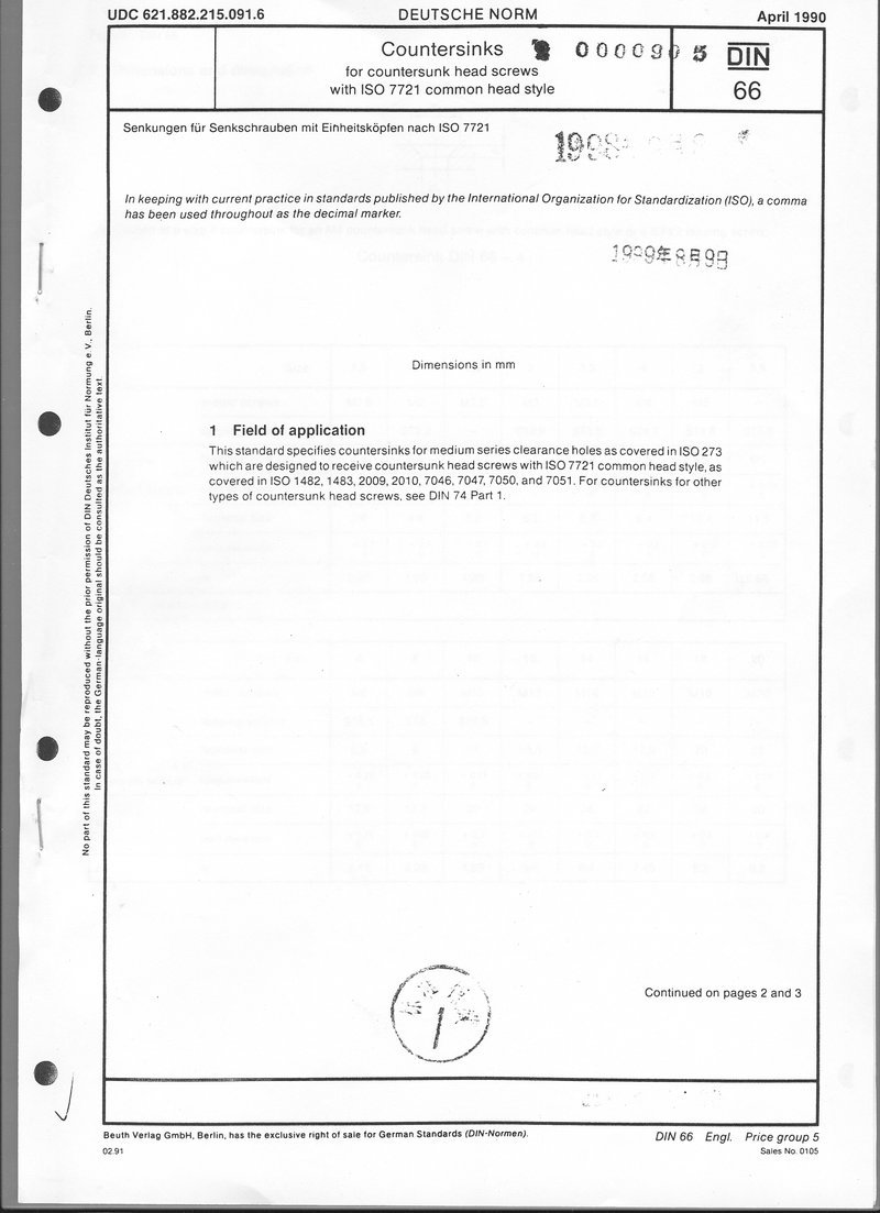
下载标准文件
din-66(1)
英语 · PDF · 6 页 · 12.58 MB