din-105-3(1)
粘土砖 - 高强度砖和高强度工程砖
din-105-3(1)
Clay bricks - High strength bricks and high strength engineering bricks
标准信息
STANDARD INFORMATION- 标准编号
- din-105-3(1)
- 所属分类
- DIN 德国标准
- 发布机构
- DIN
- 版本年份
- 1982
- 文件语言
- 英语
- 文件格式
- 文件页数
- 6 页
- 文件大小
- 22.93 MB
中文名称为参考译名,文件语言以原文为准。
· 更新:
标准简介
OVERVIEW中文简介
该标准规定了高强度粘土砖和高强度工程砖的定义、分类、尺寸要求、性能指标(如抗压强度和表观密度)及标记方法。它适用于承重和非承重砌体结构,特别是用于高应力外墙和内墙的建筑材料。
English summary
This standard specifies the definitions, classifications, dimensional requirements, performance criteria (such as compressive strength and apparent density), and marking methods for high-strength clay bricks and high-strength engineering bricks. It applies to building materials used in load-bearing and non-load-bearing masonry, particularly for highly stressed external and internal walls.
以上为根据文件整理的内容简介。
相关标签
标准内容预览
DOCUMENT PREVIEWClay bricks
High strength bricks and high strength engineering bricks
DIN 105 Part 3
Mauerziegel; hochfeste Ziegel und hochfeste Klinker
Supersedes July 1975 edition
In keeping with current practice in standards published by the International Organization for Standardization (ISO), a comma has been used throughout as the decimal marker.
This standard has been recommended to the Laender building inspectorates by the Institut für Bautechnik (Institute for Building Technology) for inclusion in the Laender building regulations.
The repeated reference to DIN 105 Part 1 relates to the November 1982 edition.
Dimensions in mm
Contents
| Page | Page |
|---|---|
| 1 Field of application | 5 Marking |
| 2 Concept | 6 Testing |
| 3 Requirements | 7 Inspection |
| 4 Designation | 8 Delivery note |
1 Field of application
High strength clay bricks and high strength engineering bricks are building materials for loadbearing and non-loadbearing brickwork. They are specially suited for the construction of highly stressed external and internal walls.
2 Concept
High strength clay bricks and high strength engineering bricks are bricks which are moulded from clay, loam or clayey substances, with or without additives, and fired. The additives shall have no long-term deleterious effect on the properties of the clay bricks. The apparent brick density shall correspond at least to apparent density class 1,21) and the compressive strength shall correspond at least to compressive strength class 362).
3 Requirements
3.1 Shape
High strength clay bricks and high strength engineering bricks shall have the shape of a unit defined by rectangles (this does not apply to purpose-made bricks). The end faces of bricks in formats not less than 8 DF may be provided with recesses for mortar. Grooves or similar may be provided on the stretcher faces to improve plaster adhesion.
1) See table 3.
2) See table 4.
3.2 Types of brick
3.2.1 Solid bricks are bricks the cross section of which may be reduced by up to 15 % through perforations vertical to the bed face.
3.2.2 Vertically perforated bricks are bricks which are perforated vertically to the bed face. They may have A, B or C type perforations (see table 1).
3.2.3 Panel wall bricks are bricks designed for building panel walls as specified in DIN 1053 Part 4.
3.2.4 Purpose-made bricks are bricks which deviate from the shape described in subclause 3.1 for reasons of their intended use.
3.2.5 Facing bricks are bricks for which frost resistance has been verified by testing. The surfaces may be textured.
3.2.6 High strength engineering bricks are surface-sintered bricks (water absorption up to approximately 7 % by mass) the frost resistance of which has been verified by testing. In addition, they shall fulfill special requirements with regard to the apparent density of body (see subclause 3.5.2). The surfaces may be textured.
3.3 Perforations and webs
3.3.1 Perforations and webs shall conform to table 1. Perforations shall be distributed over the bed face as evenly as possible; they may be of any cross-sectional shape.
Continued on pages 2 to 6
1
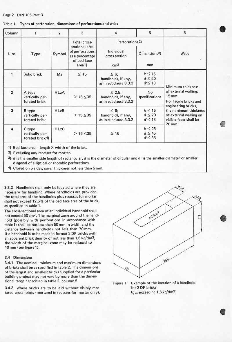
Table 1. Types of perforation, dimensions of perforations and webs
| Column | 1 | 2 | 3 | 4 | 5 | 6 |
|---|---|---|---|---|---|---|
| Line | Type | Symbol | Total cross-sectional area of perforations, as a percentage of bed face area1) | Perforations2) Individual cross section cm2 |
Dimensions3) mm |
Webs |
| 1 | Solid brick | Mz | ≤ 15 | ≤ 6; handholds, if any, as in subclause 3.3.2 | k ≤ 15 d ≤ 20 d' ≤ 18 |
Minimum thickness of external walling: 15 mm. For facing bricks and engineering bricks, the minimum thickness of external walling on visible faces shall be 20 mm. |
| 2 | A type vertically perforated brick | HLzA | > 15 ≤ 35 | ≤ 2,5; handholds, if any, as in subclause 3.3.2 | No specifications | |
| 3 | B type vertically perforated brick | HLzB | > 15 ≤ 35 | ≤ 6; handholds, if any, as in subclause 3.3.2 | k ≤ 15 d ≤ 20 d' ≤ 18 |
|
| 4 | C type vertically perforated brick4) | HLzC | > 15 ≤ 35 | ≤ 16 | k ≤ 25 d ≤ 45 d' ≤ 35 |
|
|
1) Bed face area = length × width of the brick. 2) Excluding any recesses for mortar. 3) k is the smaller side length of rectangular, d is the diameter of circular and d' is the smaller diameter or smaller diagonal of elliptical or rhombic perforations. 4) Closed on 5 sides; cover thickness not less than 5 mm. |
||||||
3.3.2 Handholds
Handholds shall only be located where they are necessary for handling. Where handholds are provided, the total area of the handholds plus recesses for mortar shall not exceed 12,5 % of the bed face area of the brick, as specified in table 1.
The cross-sectional area of an individual handhold shall not exceed 50 cm2. The marginal zone around the handhold (possibly with perforations in accordance with table 1) shall be not less than 50 mm in width and the distance between handholds not less than 70 mm. If a handhold is to be made in format 2 DF bricks with an apparent brick density of not less than 1,6 kg/dm3, the width of the marginal zone may be reduced to 40 mm (see figure 1).
3.4 Dimensions
3.4.1 The nominal, minimum and maximum dimensions of bricks shall be as specified in table 2. The dimensions of the largest and smallest bricks supplied for a particular building project may not vary by more than the dimensional range t specified in table 2, column 5.
3.4.2 Where bricks are to be laid without visibly mortared cross joints (mortared in recesses for mortar only),
Figure 1. Example of the location of a handhold for 2 DF bricks (qzi exceeding 1,6 kg/dm3)
2
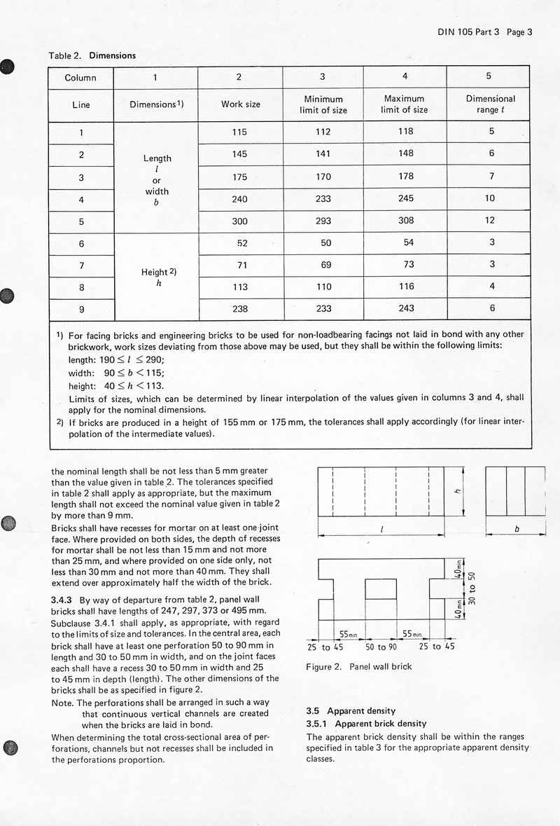
Table 2. Dimensions
| Column | 1 | 2 | 3 | 4 | 5 |
|---|---|---|---|---|---|
| Line | Dimensions 1) | Work size | Minimum limit of size | Maximum limit of size | Dimensional range t |
| 1 | Length l or width b | 115 | 112 | 118 | 5 |
| 2 | 145 | 141 | 148 | 6 | |
| 3 | 175 | 170 | 178 | 7 | |
| 4 | 240 | 233 | 245 | 10 | |
| 5 | 300 | 293 | 308 | 12 | |
| 6 | Height 2) h | 52 | 50 | 54 | 3 |
| 7 | 71 | 69 | 73 | 3 | |
| 8 | 113 | 110 | 116 | 4 | |
| 9 | 238 | 233 | 243 | 6 |
1) For facing bricks and engineering bricks to be used for non-loadbearing facings not laid in bond with any other brickwork, work sizes deviating from those above may be used, but they shall be within the following limits: length: 190 ≤ l ≤ 290; width: 90 ≤ b < 115; height: 40 ≤ h < 113. Limits of sizes, which can be determined by linear interpolation of the values given in columns 3 and 4, shall apply for the nominal dimensions.
2) If bricks are produced in a height of 155 mm or 175 mm, the tolerances shall apply accordingly (for linear interpolation of the intermediate values).
the nominal length shall be not less than 5 mm greater than the value given in table 2. The tolerances specified in table 2 shall apply as appropriate, but the maximum length shall not exceed the nominal value given in table 2 by more than 9 mm.
Bricks shall have recesses for mortar on at least one joint face. Where provided on both sides, the depth of recesses for mortar shall be not less than 15 mm and not more than 25 mm, and where provided on one side only, not less than 30 mm and not more than 40 mm. They shall extend over approximately half the width of the brick.
3.4.3
By way of departure from table 2, panel wall bricks shall have lengths of 247, 297, 373 or 495 mm. Subclause 3.4.1 shall apply, as appropriate, with regard to the limits of size and tolerances. In the central area, each brick shall have at least one perforation 50 to 90 mm in length and 30 to 50 mm in width, and on the joint faces each shall have a recess 30 to 50 mm in width and 25 to 45 mm in depth (length). The other dimensions of the bricks shall be as specified in figure 2.
Note. The perforations shall be arranged in such a way that continuous vertical channels are created when the bricks are laid in bond.
When determining the total cross-sectional area of perforations, channels but not recesses shall be included in the perforations proportion.
Figure 2. Panel wall brick
3.5 Apparent density
3.5.1 Apparent brick density
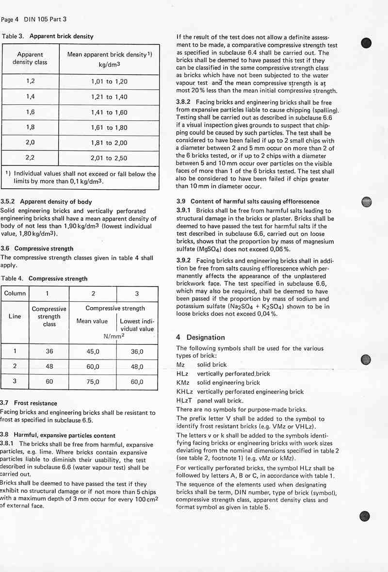
The apparent brick density shall be within the ranges specified in table 3 for the appropriate apparent density classes.
3
Page 4 DIN 105 Part 3
Table 3. Apparent brick density
3.5.2 Apparent density of bodySolid engineering bricks and vertically perforated engineering bricks shall have a mean apparent density of body of not less than 1,90 kg/dm3 (lowest individual value, 1,80 kg/dm3). 3.6 Compressive strengthThe compressive strength classes given in table 4 shall apply. Table 4. Compressive strength
3.7 Frost resistanceFacing bricks and engineering bricks shall be resistant to frost as specified in subclause 6.5. 3.8 Harmful, expansive particles content3.8.1The bricks shall be free from harmful, expansive particles, e.g. lime. Where bricks contain expansive particles liable to diminish their usability, the test described in subclause 6.6 (water vapour test) shall be carried out. Bricks shall be deemed to have passed the test if they exhibit no structural damage or if not more than 5 chips with a maximum depth of 3 mm occur for every 100 cm2 of external face. |
If the result of the test does not allow a definite assessment to be made, a comparative compressive strength test as specified in subclause 6.4 shall be carried out. The bricks shall be deemed to have passed this test if they can be classified in the same compressive strength class as bricks which have not been subjected to the water vapour test and the mean compressive strength is at most 20 % less than the mean initial compressive strength. 3.8.2Facing bricks and engineering bricks shall be free from expansive particles liable to cause chipping (spalling). Testing shall be carried out as described in subclause 6.6 if a visual inspection gives grounds to suspect that chipping could be caused by such particles. The test shall be considered to have been failed if up to 2 small chips with a diameter between 2 and 5 mm occur on more than 2 of the 6 bricks tested, or if up to 2 chips with a diameter between 5 and 10 mm occur over particles on the visible faces of more than 1 of the 6 bricks tested. The test shall also be considered to have been failed if chips greater than 10 mm in diameter occur. 3.9 Content of harmful salts causing efflorescence3.9.1Bricks shall be free from harmful salts leading to structural damage in the bricks or plaster. Bricks shall be deemed to have passed the test for harmful salts if the test described in subclause 6.6, carried out on loose bricks, shows that the proportion by mass of magnesium sulfate (MgSO4) does not exceed 0,06 %. 3.9.2Facing bricks and engineering bricks shall in addition be free from salts causing efflorescence which permanently affects the appearance of the unplastered brickwork face. The test specified in subclause 6.6, which may also be required, shall be deemed to have been passed if the proportion by mass of sodium and potassium sulfate (Na2SO4 + K2SO4) shown to be in loose bricks does not exceed 0,04 %. 4 DesignationThe following symbols shall be used for the various types of brick: Mz solid brick HLz vertically perforated brick KMz solid engineering brick KHLz vertically perforated engineering brick HLzT panel wall brick. There are no symbols for purpose-made bricks. The prefix letter V shall be added to the symbol to identify frost resistant bricks (e.g. VMz or VHLz). The letters v or k shall be added to the symbols identifying facing bricks or engineering bricks with work sizes deviating from the nominal dimensions specified in table 2 (see table 2, footnote 1) (e.g. vMz or kMz). For vertically perforated bricks, the symbol HLz shall be followed by letters A, B or C, in accordance with table 1. The sequence of the elements used when designating bricks shall be term, DIN number, type of brick (symbol), compressive strength class, apparent density class and format symbol as given in table 5. |
||||||||||||||||||||||||||||||||||||||||||||
4
DIN 105 Part 3
Table 5. Format symbols (examples)
Examples of designation: Designation of a solid brick (Mz) of compressive strength class 60, apparent density class 1,8, length l = 240 mm, width b = 115 mm and height h = 113 mm (2 DF): Brick DIN 105 — Mz 60 — 1,8 — 2 DF Designation of a vertically perforated brick (HLz) of perforation type B, compressive strength class 36, apparent density class 1,4, length l = 240 mm, width b = 300 mm and height h = 113 mm (5 DF): Brick DIN 105 — HLzB 36 — 1,4 — 5 DF 5 MarkingAll bricks (excluding bricks for brickwork to remain visible) shall be provided with a works mark (manufacturer's mark). Bricks ready for dispatch shall additionally be marked on one stretcher face with a colour coding stripe not less than 20 mm in width, indicating their compressive strength class (see table 6), and details of their apparent density class. It is sufficient if one brick is marked for up to 200 bricks. If bricks are packaged, it shall be deemed sufficient if the packaging or an attached label contains the works mark, the apparent density class and compressive strength class; the same shall apply for facing bricks and engineering bricks. |
Table 6. Colour coding
6 Testing6.1 Shape, dimensions and perforationIn accordance with DIN 105 Part 1. 6.2 Apparent brick densityIn accordance with DIN 105 Part 1. 6.3 Apparent density of bodyIn accordance with DIN 105 Part 1. 6.4 Compressive strengthIn accordance with DIN 105 Part 1. 6.5 Frost resistanceIn accordance with DIN 105 Part 1. 6.6 Expansive particles and water-soluble saltsIn accordance with DIN 105 Part 1. 7 Inspection7.1 GeneralSee DIN 105 Part 1. 7.2 Internal controlIn accordance with DIN 105 Part 1. If, instead of the compressive strength test, an alternative method of test as specified in DIN 105 Part 1, subclause 7.2.1, footnote 3, is used, the compressive strength shall additionally be tested as specified in subclause 6.4 on 6 bricks at quarter year intervals. 7.3 Third party inspectionIn accordance with DIN 105 Part 1. 8 Delivery noteIn accordance with DIN 105 Part 1. |
||||||||||||||||||||||||||||||||||||||||||||||||||||
5
Standards referred to
DIN 105 Part 1 Clay bricks; solid bricks and vertically perforated bricks
DIN 1053 Part 4 Masonry; buildings of prefabricated brickwork components
Previous editions
DIN 105 Part 3: 04.74; 07.75
Amendments
The following amendments have been made in comparison with the July 1975 edition:
The specifications relating to the designation, marking, testing, inspection and the delivery note have been aligned with DIN 105 Part 1, November 1982 edition.
International Patent Classification
E 04 C 1-00
6
预览内容由文件识别整理,表格、公式及文字请以原始文件为准。
原文图片预览
PAGE IMAGES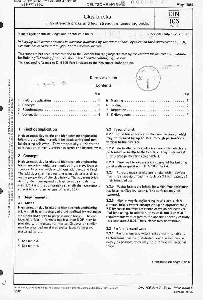
下载标准文件
din-105-3(1)
英语 · PDF · 6 页 · 22.93 MB