DIN 2609
钢对接焊接管件 技术交货条件
DIN 2609
Steel butt-welding pipe fittings Technical delivery conditions
标准信息
STANDARD INFORMATION- 标准编号
- DIN 2609
- 所属分类
- DIN 德国标准
- 发布机构
- DIN
- 版本年份
- 1997
- 文件语言
- 英语
- 文件格式
- 文件页数
- 6 页
- 文件大小
- 4.41 MB
中文名称为参考译名,文件语言以原文为准。
· 更新:
标准简介
OVERVIEW中文简介
该标准规定了符合DIN 2605、DIN 2615、DIN 2616或DIN 2617标准的非合金钢和合金钢对接焊接管件的技术交货条件。内容涵盖了材料要求、制造工艺(包括焊接、成型、机加工)、化学成分、机械性能、表面状态、尺寸公差以及测试和材料检验证书的要求。
English summary
This standard specifies the technical delivery conditions for unalloyed and alloyed steel butt-welding pipe fittings in compliance with DIN 2605, DIN 2615, DIN 2616, or DIN 2617. It covers requirements for materials, manufacturing processes (including welding, forming, and machining), chemical composition, mechanical properties, surface condition, dimensional tolerances, as well as testing and materials testing certificates.
以上为根据文件整理的内容简介。
相关标签
标准内容预览
DOCUMENT PREVIEWSteel butt-welding pipe fittings
Technical delivery conditions
DIN 2609
Formstücke zum Einschweißen; technische Lieferbedingungen
In keeping with current practice in standards published by the International Organization for Standardization (ISO), a comma has been used throughout as the decimal marker.
The symbol ■ denotes items which shall, symbol ■■ denoting items which may, be agreed upon at the time of ordering.
Contents
|
Page
|
Page
|
1 Field of application
This standard specifies technical delivery conditions for unalloyed and alloyed steel butt-welding pipe fittings in compliance with DIN 2605 Part 1 or 2, DIN 2615 Part 1 or 2 (at present at the stage of draft), DIN 2616 Part 1 or 2, or DIN 2617. Where such fittings fall under the scope of the regulations pertaining to plants subject to mandatory inspection as referred to in section 24 of the Gewerbeordnung (German Trade Regulation), such as the Dampfkesselverordnung (German Regulation on steam boilers) or the Druckbehälterverordnung (German Pressure Vessels Regulation), then the requirements given in the relevant codes of practice, such as the Technische Regeln Dampfkessel (Codes of practice for steam boilers), the Technische Regeln Druckbehälter (Codes of practice for pressure vessels), or the AD-Merkblätter (AD Instruction sheets) shall be complied with. This also applies to fields of application where additional requirements are to be complied with.
Note. Owing to the tendency of certain materials to scale and owing to stresses under service conditions possibly deviating from those on which the specifications of this standard are based, the design temperature ranges specified in table 2 may not apply in all cases.
2 Ordering
It shall be the purchaser's responsibility to determine which items are to be included in the order.
■ The standard designation as given in the relevant dimensional standard, the desired number of fittings, the type of DIN 50 049 materials testing certificate and, if necessary, any other relevant codes of practice shall be given in the order.
Continued on pages 2 to 11
1
3 Materials
The materials to be used for the fittings covered here are given in table 2.
Where materials other than those given in table 2 are to be used, the specifications of this standard shall still apply.
The various forms of semi-finished products from which fittings are to be made are given as material groups, which are identified by a material designation and a code letter which is to be used for marking purposes.
4 Requirements
4.1 Manufacturing process
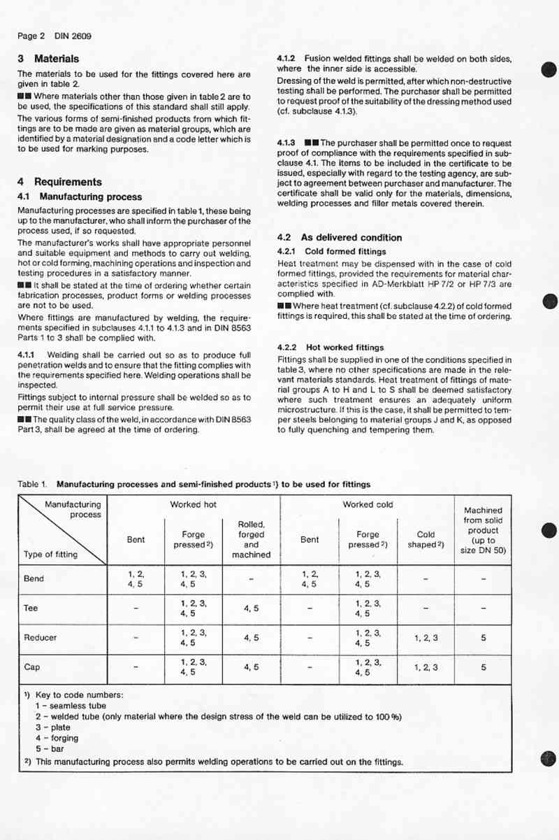
Manufacturing processes are specified in table 1, these being up to the manufacturer, who shall inform the purchaser of the process used, if so requested.
The manufacturer's works shall have appropriate personnel and suitable equipment and methods to carry out welding, hot or cold forming, machining operations and inspection and testing procedures in a satisfactory manner.
It shall be stated at the time of ordering whether certain fabrication processes, product forms or welding processes are not to be used.
Where fittings are manufactured by welding, the requirements specified in subclauses 4.1.1 to 4.1.3 and in DIN 8563 Parts 1 to 3 shall be complied with.
4.1.1 Welding
Welding shall be carried out so as to produce full penetration welds and to ensure that the fitting complies with the requirements specified here. Welding operations shall be inspected.
Fittings subject to internal pressure shall be welded so as to permit their use at full service pressure.
The quality class of the weld, in accordance with DIN 8563 Part 3, shall be agreed at the time of ordering.
4.1.2 Fusion welded fittings
Fusion welded fittings shall be welded on both sides, where the inner side is accessible.
Dressing of the weld is permitted, after which non-destructive testing shall be performed. The purchaser shall be permitted to request proof of the suitability of the dressing method used (cf. subclause 4.1.3).
4.1.3
The purchaser shall be permitted once to request proof of compliance with the requirements specified in subclause 4.1. The items to be included in the certificate to be issued, especially with regard to the testing agency, are subject to agreement between purchaser and manufacturer. The certificate shall be valid only for the materials, dimensions, welding processes and filler metals covered therein.
4.2 As delivered condition
4.2.1 Cold formed fittings
Heat treatment may be dispensed with in the case of cold formed fittings, provided the requirements for material characteristics specified in AD-Merkblatt HP 7/2 or HP 7/3 are complied with.
Where heat treatment (cf. subclause 4.2.2) of cold formed fittings is required, this shall be stated at the time of ordering.
4.2.2 Hot worked fittings
Fittings shall be supplied in one of the conditions specified in table 3, where no other specifications are made in the relevant materials standards. Heat treatment of fittings of material groups A to H and L to S shall be deemed satisfactory where such treatment ensures an adequately uniform microstructure. If this is the case, it shall be permitted to temper steels belonging to material groups J and K, as opposed to fully quenching and tempering them.
| Type of fitting | Worked hot | Worked cold | Machined from solid product (up to size DN 50) | ||||
|---|---|---|---|---|---|---|---|
| Bent | Forge pressed 2) | Rolled, forged and machined | Bent | Forge pressed 2) | Cold shaped 2) | ||
| Bend | 1, 2, 4, 5 | 1, 2, 3, 4, 5 | - | 1, 2, 4, 5 | 1, 2, 3, 4, 5 | - | - |
| Tee | - | 1, 2, 3, 4, 5 | 4, 5 | - | 1, 2, 3, 4, 5 | - | - |
| Reducer | - | 1, 2, 3, 4, 5 | 4, 5 | - | 1, 2, 3, 4, 5 | 1, 2, 3 | 5 |
| Cap | - | 1, 2, 3, 4, 5 | 4, 5 | - | 1, 2, 3, 4, 5 | 1, 2, 3 | 5 |
1) Key to code numbers:
1 - seamless tube
2 - welded tube (only material where the design stress of the weld can be utilized to 100 %)
3 - plate
4 - forging
5 - bar
2) This manufacturing process also permits welding operations to be carried out on the fittings.
2
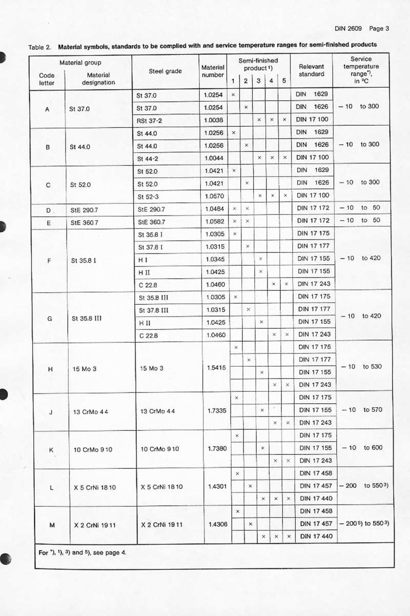
Table 2. Material symbols, standards to be complied with and service temperature ranges for semi-finished products
| Code letter | Material designation | Steel grade | Material number | Semi-finished product 1) | Relevant standard | Service temperature range 2), in °C | ||||
|---|---|---|---|---|---|---|---|---|---|---|
| 1 | 2 | 3 | 4 | 5 | ||||||
| A | St 37.0 | St 37.0 | 1.0254 | x | DIN 1629 | -10 to 300 | ||||
| St 37.0 | 1.0254 | x | DIN 1626 | |||||||
| RSt 37-2 | 1.0038 | x | x | x | DIN 17 100 | |||||
| B | St 44.0 | St 44.0 | 1.0256 | x | DIN 1629 | -10 to 300 | ||||
| St 44.0 | 1.0256 | x | DIN 1626 | |||||||
| St 44-2 | 1.0044 | x | x | x | DIN 17 100 | |||||
| C | St 52.0 | St 52.0 | 1.0421 | x | DIN 1629 | -10 to 300 | ||||
| St 52.0 | 1.0421 | x | DIN 1626 | |||||||
| St 52-3 | 1.0570 | x | x | x | DIN 17 100 | |||||
| D | StE 290.7 | StE 290.7 | 1.0484 | x | x | DIN 17 172 | -10 to 50 | |||
| E | StE 360.7 | StE 360.7 | 1.0582 | x | x | DIN 17 172 | -10 to 50 | |||
| F | St 35.8 I | St 35.8 I | 1.0305 | x | DIN 17 175 | -10 to 420 | ||||
| St 37.8 I | 1.0315 | x | DIN 17 177 | |||||||
| H I | 1.0345 | x | DIN 17 155 | |||||||
| H II | 1.0425 | x | DIN 17 155 | |||||||
| C 22.8 | 1.0460 | x | x | DIN 17 243 | ||||||
| G | St 35.8 III | St 35.8 III | 1.0305 | x | DIN 17 175 | -10 to 420 | ||||
| St 37.8 III | 1.0315 | x | DIN 17 177 | |||||||
| H II | 1.0425 | x | DIN 17 155 | |||||||
| C 22.8 | 1.0460 | x | x | DIN 17 243 | ||||||
| H | 15 Mo 3 | 15 Mo 3 | 1.5415 | x | DIN 17 175 | -10 to 530 | ||||
| x | DIN 17 177 | |||||||||
| x | DIN 17 155 | |||||||||
| x | x | DIN 17 243 | ||||||||
| J | 13 CrMo 44 | 13 CrMo 44 | 1.7335 | x | DIN 17 175 | -10 to 570 | ||||
| x | DIN 17 155 | |||||||||
| x | x | DIN 17 243 | ||||||||
| K | 10 CrMo 910 | 10 CrMo 910 | 1.7380 | x | DIN 17 175 | -10 to 600 | ||||
| x | DIN 17 155 | |||||||||
| x | x | DIN 17 243 | ||||||||
| L | X 5 CrNi 18 10 | X 5 CrNi 18 10 | 1.4301 | x | DIN 17 458 | -200 to 550 3) | ||||
| x | DIN 17 457 | |||||||||
| x | x | x | DIN 17 440 | |||||||
| M | X 2 CrNi 19 11 | X 2 CrNi 19 11 | 1.4306 | x | DIN 17 458 | -200 5) to 550 3) | ||||
| x | DIN 17 457 | |||||||||
| x | x | x | DIN 17 440 | |||||||
For *), 1), 3) and 5), see page 4.
3
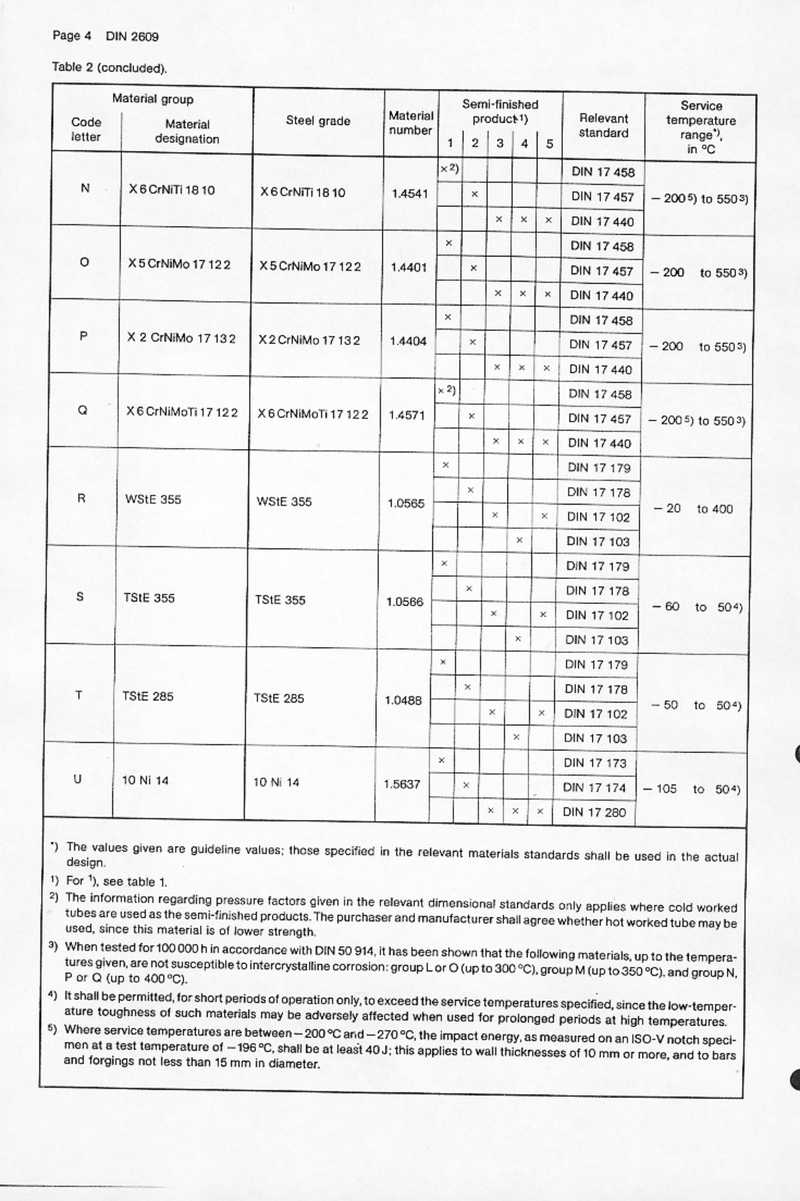
Table 2 (concluded).
| Code letter | Material designation | Steel grade | Material number | Semi-finished product1) | Relevant standard | Service temperature range*), in °C | ||||
|---|---|---|---|---|---|---|---|---|---|---|
| 1 | 2 | 3 | 4 | 5 | ||||||
| N | X 6 CrNiTi 18 10 | X 6 CrNiTi 18 10 | 1.4541 | x 2) | DIN 17 458 | – 2005) to 5503) | ||||
| x | DIN 17 457 | |||||||||
| x | x | x | DIN 17 440 | |||||||
| O | X 5 CrNiMo 17 12 2 | X 5 CrNiMo 17 12 2 | 1.4401 | x | DIN 17 458 | – 200 to 5503) | ||||
| x | DIN 17 457 | |||||||||
| x | x | x | DIN 17 440 | |||||||
| P | X 2 CrNiMo 17 13 2 | X 2 CrNiMo 17 13 2 | 1.4404 | x | DIN 17 458 | – 200 to 5503) | ||||
| x | DIN 17 457 | |||||||||
| x | x | x | DIN 17 440 | |||||||
| Q | X 6 CrNiMoTi 17 12 2 | X 6 CrNiMoTi 17 12 2 | 1.4571 | x 2) | DIN 17 458 | – 2005) to 5503) | ||||
| x | DIN 17 457 | |||||||||
| x | x | x | DIN 17 440 | |||||||
| R | WStE 355 | WStE 355 | 1.0565 | x | DIN 17 179 | – 20 to 400 | ||||
| x | DIN 17 178 | |||||||||
| x | x | DIN 17 102 | ||||||||
| x | DIN 17 103 | |||||||||
| S | TStE 355 | TStE 355 | 1.0566 | x | DIN 17 179 | – 60 to 504) | ||||
| x | DIN 17 178 | |||||||||
| x | x | DIN 17 102 | ||||||||
| x | DIN 17 103 | |||||||||
| T | TStE 285 | TStE 285 | 1.0488 | x | DIN 17 179 | – 50 to 504) | ||||
| x | DIN 17 178 | |||||||||
| x | x | DIN 17 102 | ||||||||
| x | DIN 17 103 | |||||||||
| U | 10 Ni 14 | 10 Ni 14 | 1.5637 | x | DIN 17 173 | – 105 to 504) | ||||
| x | DIN 17 174 | |||||||||
| x | x | x | DIN 17 280 | |||||||
*) The values given are guideline values; those specified in the relevant materials standards shall be used in the actual design.
1) For 1), see table 1.
2) The information regarding pressure factors given in the relevant dimensional standards only applies where cold worked tubes are used as the semi-finished products. The purchaser and manufacturer shall agree whether hot worked tube may be used, since this material is of lower strength.
3) When tested for 100 000 h in accordance with DIN 50 914, it has been shown that the following materials, up to the temperatures given, are not susceptible to intercrystalline corrosion: group L or O (up to 300 °C), group M (up to 350 °C), and group N, P or Q (up to 400 °C).
4) It shall be permitted, for short periods of operation only, to exceed the service temperatures specified, since the low-temperature toughness of such materials may be adversely affected when used for prolonged periods at high temperatures.
5) Where service temperatures are between – 200 °C and – 270 °C, the impact energy, as measured on an ISO-V notch specimen at a test temperature of – 196 °C, shall be at least 40 J; this applies to wall thicknesses of 10 mm or more, and to bars and forgings not less than 15 mm in diameter.
4
Table 3. Heat treatment conditions
| As delivered condition | Material group | Code letter |
|---|---|---|
| Normalized or worked at normalizing temperature | A to H R to S |
N |
| Quenched and tempered | J, K, U | V |
| Heat treated in solution | L to Q | L |
| Quenched and tempered or normalized | T | V, N |
4.3 Chemical composition
The chemical composition of semi-finished products shall be as specified in the relevant materials standards.
It may be agreed to determine the chemical composition by product analysis, with specimens taken from either the semi-finished product or the fitting.
4.4 Mechanical properties
The material used shall have the mechanical properties specified in the relevant standard (cf. table 2). The impact strength of the weld metal shall be that of the parent metal, as measured on a test piece taken transverse to the direction of rolling.
4.5 Weldability
Information regarding weldability shall be obtained from the relevant standard (cf. table 2).
4.6 Surface condition
4.6.1 Fittings shall have a smooth inner and outer surface consistent with the manufacturing process used.
4.6.2 Slight irregularities in the surface (e.g. depressions, raised areas or shallow grooves) resulting from the manufacturing process used are permitted, provided the wall thickness is maintained within the tolerances specified.
4.6.3 Proper removal of shallow surface defects using appropriate means is permitted, provided the remaining wall thickness is maintained within the tolerances specified. The purchaser's consent shall be required for the dressing of welds.
4.6.4 Any further requirements on the surface finish shall be the subject of agreement.
4.7 Dimensions and tolerances
4.7.1 Dimensions
Fittings shall have the dimensions specified in the relevant dimensional standard.
4.7.2 Tolerances
4.7.2.1 Fittings shall be manufactured to the tolerances specified in the relevant dimensional standard.
4.7.2.2 The limit deviations for the outer diameter of the fitting ends are specified in table 4 (taken from DIN 1629). The upper limit deviation for wall thickness at the fitting end (dimensions s, s1 and s2) shall be equal to 15 % of the nominal wall thickness for all nominal sizes.
4.7.2.3 To ensure that flow is not obstructed, the inner diameter of fittings (except for caps) shall be at least 80 %, or 70 % in the case of tees, of the theoretical inner diameter of the pipe to be welded on. These values account for the upper limit deviations of wall thicknesses s3, s4, s1 and su.
The theoretical inner diameter of the connecting pipe shall be calculated from da minus twice the nominal wall thickness.
4.7.2.4 The tolerances on circularity at the fitting end(s) shall be as specified in table 4 (taken from DIN 1626), that for elbows and bends being 4 % along the length of the fitting.
The out-of-roundness, R, as a percentage, shall be calculated from the following formula:
R = 200 · (da max − da min) / (da max + da min) (1)
where da max is the greatest outer diameter, and da min is the smallest outer diameter, measured in one plane.
4.7.2.5 Fittings shall be produced to form tolerance Q as specified in table 5 (cf. figures 1 to 7 for notation), measurements being made with the fittings placed against two surfaces normal to each other. Q shall not be exceeded at any point about the circumference of the fitting. Where Q is checked, the other fitting dimensions shall also be checked for compliance with the relevant dimensional standards. The subscripts given along with Q in figures 1 to 7 denote the dimension in the relevant dimensional standard to which Q refers.
Table 4. Limit deviations for outer diameter and circularity tolerance
| Outer diameter, da, in mm | Limit deviations for outer diameter | Tolerance on circularity | |
|---|---|---|---|
| Subject to agreement. | |||
| ≤ 100 | ± 1 % da (with a maximum of ± 0,5 mm) |
± 0,4 mm | Within the specified tolerance on diameter. |
| 100 < da ≤ 200 | ± 1 % da | ± 0,5 % da | |
| > 200 | ± 1 % da | ± 0,6 % da | 2 % |
5
4.7.3 Waviness
It shall be permitted for elbows and bends to exhibit shallow waves as illustrated in figure 8, provided that the mean wave height, hm, does not exceed 3 % of da1 (cf. equation 2):
hm = (da2 + da4) / 2 − da3 (2)
where
L is greater than or equal to 15 · hm (3)
Figure 8.
| Tolerance Q | |
|---|---|
| Standard design | 1 % of dimension (with a maximum of 1 mm) |
| Subject to agreement. | 0,5 % of dimension (with a maximum of 0,5 mm) |
4.7.4 Design of welding ends
The standard design of welding ends shall be so as to produce the following groove shapes (given as a function of the wall thickness ordered):
up to 3 mm: DIN 2559-1 groove shape;
over 3 mm up to 16 mm: DIN 2559-22 groove shape;
over 16 mm: DIN 2559-3 groove shape.
Other groove shapes shall be the subject of agreement.
5 Testing and materials testing certificates
5.1 General
Fittings complying with this standard may be supplied along with one of the following DIN 50 049 materials testing certificates:
a) certificate DIN 50 049-2.2 (test report);
b) certificate DIN 50 049-3.1 A (inspection certificate A);
c) certificate DIN 50 049-3.1 B (inspection certificate B);
d) certificate DIN 50 049-3.1 C (inspection certificate C).
The type of certificate and, in the case of third-party acceptance inspection, the inspection agency shall be stated at the time of ordering.
5.2 Test site
Testing of fittings shall be conducted at the manufacturer's works.
5.3 Scope of testing
5.3.1 Where fittings are to be supplied along with a DIN 50 049 test report, this shall give the values of yield strength, tensile strength and elongation after fracture and, if
6
预览内容由文件识别整理,表格、公式及文字请以原始文件为准。
原文图片预览
PAGE IMAGES
下载标准文件
DIN 2609
英语 · PDF · 6 页 · 4.41 MB