标准信息
STANDARD INFORMATION- 标准编号
- DIN 186(1)
- 所属分类
- DIN 德国标准
- 发布机构
- DIN
- 版本年份
- 1997
- 文件语言
- 英语
- 文件格式
- 文件页数
- 6 页
- 文件大小
- 15.42 MB
中文名称为参考译名,文件语言以原文为准。
· 更新:
标准简介
OVERVIEW中文简介
该标准规定了M6至M48规格方颈T型螺栓的尺寸、公差及技术要求。适用于通过T型槽将部件固定到基础或类似结构中的可拆卸连接场景。
English summary
This standard specifies dimensions, tolerances, and technical requirements for T-head bolts with square neck ranging from M6 to M48. It applies to detachable fastening applications where components are attached to foundations or similar structures using T-slots.
以上为根据文件整理的内容简介。
相关标签
标准内容预览
DOCUMENT PREVIEWT-head bolts with square neck
Hammerschrauben mit Vierkant
Supersedes January 1987 edition.
In keeping with current practice in standards published by the International Organization for Standardization (ISO), a comma has been used throughout as the decimal marker.
Dimensions in mm
1 Scope and field of application
This standard specifies M 6 to M 48 T-head bolts with square neck. They are designed for use in attaching components to foundations or similar structures by means of T-slots (such as are specified in DIN 649), where T-head bolts with square neck are considered adequate detachable fasteners.
2 Dimensions
Type A, with thread end
DIN 78 – K or DIN 78 – L thread end, at the manufacturer's discretion.
u (incomplete thread); 2P maximum.
Type B, with shank fully threaded
Continued on pages 2 to 4
Beuth Verlag GmbH, Berlin, has the exclusive right of sale for German Standards (DIN-Normen). DIN 186 Engl. Price group 5 Sales No. 0105
1
Page 2 DIN 186
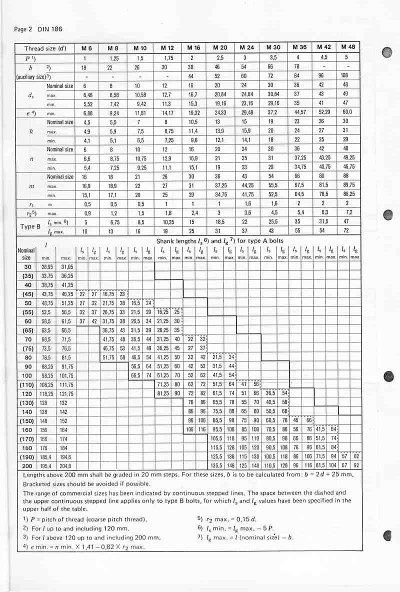
| Thread size (d) | M 6 | M 8 | M 10 | M 12 | M 16 | M 20 | M 24 | M 30 | M 36 | M 42 | M 48 | |
|---|---|---|---|---|---|---|---|---|---|---|---|---|
| P 1) | 1 | 1,25 | 1,5 | 1,75 | 2 | 2,5 | 3 | 3,5 | 4 | 4,5 | 5 | |
| b 2) | 18 | 22 | 26 | 30 | 38 | 46 | 54 | 66 | 78 | - | - | |
| (auxiliary size) 3) | - | - | - | - | 44 | 52 | 60 | 72 | 84 | 96 | 108 | |
| ds | Nominal size | 6 | 8 | 10 | 12 | 16 | 20 | 24 | 30 | 36 | 42 | 48 |
| max. | 6,48 | 8,58 | 10,58 | 12,7 | 16,7 | 20,84 | 24,84 | 30,84 | 37 | 43 | 49 | |
| min. | 5,52 | 7,42 | 9,42 | 11,3 | 15,3 | 19,16 | 23,16 | 29,16 | 35 | 41 | 47 | |
| e 4) | min. | 6,88 | 9,24 | 11,81 | 14,17 | 19,32 | 24,33 | 29,48 | 37,2 | 44,57 | 52,29 | 60,0 |
| k | Nominal size | 4,5 | 5,5 | 7 | 8 | 10,5 | 13 | 15 | 19 | 23 | 26 | 30 |
| max. | 4,9 | 5,9 | 7,5 | 8,75 | 11,4 | 13,9 | 15,9 | 20 | 24 | 27 | 31 | |
| min. | 4,1 | 5,1 | 6,5 | 7,25 | 9,6 | 12,1 | 14,1 | 18 | 22 | 25 | 29 | |
| n | Nominal size | 6 | 8 | 10 | 12 | 16 | 20 | 24 | 30 | 36 | 42 | 48 |
| max. | 6,6 | 8,75 | 10,75 | 12,9 | 16,9 | 21 | 25 | 31 | 37,25 | 43,25 | 49,25 | |
| min. | 5,4 | 7,25 | 9,25 | 11,1 | 15,1 | 19 | 23 | 29 | 34,75 | 40,75 | 46,75 | |
| m | Nominal size | 16 | 18 | 21 | 26 | 30 | 36 | 43 | 54 | 66 | 80 | 88 |
| max. | 16,9 | 18,9 | 22 | 27 | 31 | 37,25 | 44,25 | 55,5 | 67,5 | 81,5 | 89,75 | |
| min. | 15,1 | 17,1 | 20 | 25 | 29 | 34,75 | 41,75 | 52,5 | 64,5 | 78,5 | 86,25 | |
| r1 | ≈ | 0,5 | 0,5 | 0,5 | 1 | 1 | 1 | 1,6 | 1,6 | 2 | 2 | 2 |
| r2 5) | max. | 0,9 | 1,2 | 1,5 | 1,8 | 2,4 | 3 | 3,6 | 4,5 | 5,4 | 6,3 | 7,2 |
| Type B | ls min. 6) | 5 | 6,75 | 8,5 | 10,25 | 15 | 18,5 | 22 | 25,5 | 35 | 31,5 | 47 |
| lg max. | 10 | 13 | 16 | 19 | 25 | 31 | 37 | 43 | 55 | 54 | 72 |
| Nominal size | l min. | l max. | ls min. | lg max. | ls min. | lg max. | ls min. | lg max. | ls min. | lg max. | ls min. | lg max. | ls min. | lg max. | ls min. | lg max. | ls min. | lg max. | ls min. | lg max. | ls min. | lg max. | ls min. | lg max. |
|---|---|---|---|---|---|---|---|---|---|---|---|---|---|---|---|---|---|---|---|---|---|---|---|---|
| 30 | 28,95 | 31,05 | ||||||||||||||||||||||
| (35) | 33,75 | 36,25 | ||||||||||||||||||||||
| 40 | 38,75 | 41,25 | ||||||||||||||||||||||
| (45) | 43,75 | 46,25 | 22 | 27 | 16,75 | 23 | ||||||||||||||||||
| 50 | 48,75 | 51,25 | 27 | 32 | 21,75 | 28 | 16,5 | 24 | ||||||||||||||||
| (55) | 53,5 | 56,5 | 32 | 37 | 26,75 | 33 | 21,5 | 29 | 16,25 | 25 | ||||||||||||||
| 60 | 58,5 | 61,5 | 37 | 42 | 31,75 | 38 | 26,5 | 34 | 21,25 | 30 | ||||||||||||||
| (65) | 63,5 | 66,5 | 36,75 | 43 | 31,5 | 39 | 26,25 | 35 | ||||||||||||||||
| 70 | 68,5 | 71,5 | 41,75 | 48 | 36,5 | 44 | 31,25 | 40 | 22 | 32 | ||||||||||||||
| (75) | 73,5 | 76,5 | 46,75 | 53 | 41,5 | 49 | 36,25 | 45 | 27 | 37 | ||||||||||||||
| 80 | 78,5 | 81,5 | 51,75 | 58 | 46,5 | 54 | 41,25 | 50 | 32 | 42 | 21,5 | 34 | ||||||||||||
| 90 | 88,25 | 91,75 | 56,5 | 64 | 51,25 | 60 | 42 | 52 | 31,5 | 44 | ||||||||||||||
| 100 | 98,25 | 101,75 | 66,5 | 74 | 61,25 | 70 | 52 | 62 | 41,5 | 54 | ||||||||||||||
| (110) | 108,25 | 111,75 | 71,25 | 80 | 62 | 72 | 51,5 | 64 | 41 | 56 | ||||||||||||||
| 120 | 118,25 | 121,75 | 81,25 | 90 | 72 | 82 | 61,5 | 74 | 51 | 66 | 36,5 | 54 | ||||||||||||
| (130) | 128 | 132 | 76 | 86 | 65,5 | 78 | 55 | 70 | 40,5 | 58 | ||||||||||||||
| 140 | 138 | 142 | 86 | 96 | 75,5 | 88 | 65 | 80 | 50,5 | 68 | ||||||||||||||
| (150) | 148 | 152 | 96 | 106 | 85,5 | 98 | 75 | 90 | 60,5 | 78 | 46 | 66 | ||||||||||||
| 160 | 156 | 164 | 106 | 116 | 95,5 | 108 | 85 | 100 | 70,5 | 88 | 56 | 76 | 41,5 | 64 | ||||||||||
| (170) | 166 | 174 | 105,5 | 118 | 95 | 110 | 80,5 | 98 | 66 | 86 | 51,5 | 74 | ||||||||||||
| 180 | 176 | 184 | 115,5 | 128 | 105 | 120 | 90,5 | 108 | 76 | 96 | 61,5 | 84 | ||||||||||||
| (190) | 185,4 | 194,6 | 125,5 | 138 | 115 | 130 | 100,5 | 118 | 86 | 106 | 71,5 | 94 | 57 | 82 | ||||||||||
| 200 | 195,4 | 204,6 | 135,5 | 148 | 125 | 140 | 110,5 | 128 | 96 | 116 | 81,5 | 104 | 67 | 92 |
Lengths above 200 mm shall be graded in 20 mm steps. For these sizes, b is to be calculated from: b = 2d + 25 mm.
Bracketed sizes should be avoided if possible.
The range of commercial sizes has been indicated by continuous stepped lines. The space between the dashed and the upper continuous stepped line applies only to type B bolts, for which ls and lg values have been specified in the upper half of the table.
1) P = pitch of thread (coarse pitch thread).
2) For l up to and including 120 mm.
3) For l above 120 up to and including 200 mm.
4) e min. = n min. × 1,41 − 0,82 × r2 max.
5) r2 max. = 0,15 d.
6) ls min. = lg max. − 5 P.
7) lg max. = l (nominal size) − b.
2
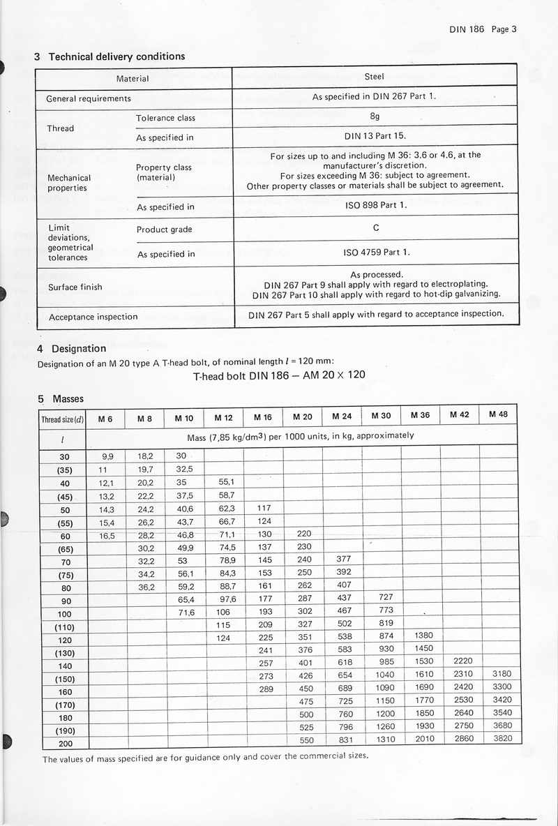
3 Technical delivery conditions
| Material | Steel |
|---|---|
| General requirements | As specified in DIN 267 Part 1. |
| Thread | Tolerance class: 8g |
| As specified in DIN 13 Part 15. | |
| Mechanical properties | Property class (material): For sizes up to and including M 36: 3,6 or 4,6, at the manufacturer's discretion. For sizes exceeding M 36: subject to agreement. Other property classes or materials shall be subject to agreement. |
| As specified in ISO 898 Part 1. | |
| Limit deviations, geometrical tolerances | Product grade: C |
| As specified in ISO 4759 Part 1. | |
| Surface finish | As processed. DIN 267 Part 9 shall apply with regard to electroplating. DIN 267 Part 10 shall apply with regard to hot-dip galvanizing. |
| Acceptance inspection | DIN 267 Part 5 shall apply with regard to acceptance inspection. |
4 Designation
Designation of an M 20 type A T-head bolt, of nominal length l = 120 mm:
T-head bolt DIN 186 – AM 20 × 120
5 Masses
| Thread size (d) | M 6 | M 8 | M 10 | M 12 | M 16 | M 20 | M 24 | M 30 | M 36 | M 42 | M 48 |
|---|---|---|---|---|---|---|---|---|---|---|---|
| l | Mass (7,85 kg/dm³) per 1000 units, in kg, approximately | ||||||||||
| 30 | 9,9 | 18,2 | 30 | ||||||||
| (35) | 11 | 19,7 | 32,5 | ||||||||
| 40 | 12,1 | 20,2 | 35 | 55,1 | |||||||
| (45) | 13,2 | 22,2 | 37,5 | 58,7 | |||||||
| 50 | 14,3 | 24,2 | 40,6 | 62,3 | 117 | ||||||
| (55) | 15,4 | 26,2 | 43,7 | 66,7 | 124 | ||||||
| 60 | 16,5 | 28,2 | 46,8 | 71,1 | 130 | 220 | |||||
| (65) | 30,2 | 49,9 | 74,5 | 137 | 230 | ||||||
| 70 | 32,2 | 53 | 78,9 | 145 | 240 | 377 | |||||
| (75) | 34,2 | 56,1 | 84,3 | 153 | 250 | 392 | |||||
| 80 | 36,2 | 59,2 | 88,7 | 161 | 262 | 407 | |||||
| 90 | 65,4 | 97,6 | 177 | 287 | 437 | 727 | |||||
| 100 | 71,6 | 106 | 193 | 302 | 467 | 773 | |||||
| (110) | 115 | 209 | 327 | 502 | 819 | ||||||
| 120 | 124 | 225 | 351 | 538 | 874 | 1380 | |||||
| (130) | 241 | 376 | 583 | 930 | 1450 | ||||||
| 140 | 257 | 401 | 618 | 985 | 1530 | 2220 | |||||
| (150) | 273 | 426 | 654 | 1040 | 1610 | 2310 | 3180 | ||||
| 160 | 289 | 450 | 689 | 1090 | 1690 | 2420 | 3300 | ||||
| (170) | 475 | 725 | 1150 | 1770 | 2530 | 3420 | |||||
| 180 | 500 | 760 | 1200 | 1850 | 2640 | 3540 | |||||
| (190) | 525 | 796 | 1260 | 1930 | 2750 | 3680 | |||||
| 200 | 550 | 831 | 1310 | 2010 | 2860 | 3820 | |||||
The values of mass specified are for guidance only and cover the commercial sizes.
3
Standards referred to
| DIN 13 Part 15 | ISO metric screw threads; fundamental deviations and tolerances for screw threads of 1 mm diameter and larger |
| DIN 78 | Thread ends; lengths of projection of thread ends for ISO metric screw threads as defined in DIN 13 |
| DIN 267 Part 1 | Fasteners; technical delivery conditions; general requirements |
| DIN 267 Part 5 | Fasteners; technical delivery conditions; acceptance inspection (modified version of ISO 3269, 1984 edition) |
| DIN 267 Part 9 | Fasteners; technical delivery conditions; components with electroplated coatings |
| DIN 267 Part 10 | Fasteners; technical delivery conditions; hot-dip galvanized components |
| DIN 649 | T-slots for T-head bolts |
| ISO 898 Part 1 | Mechanical properties of fasteners; bolts, screws and studs |
| ISO 4759 Part 1 | Tolerances for fasteners; bolts, screws and nuts with thread diameters between 1,6 mm (inclusive) and 150 mm (inclusive) and product grades A, B and C |
Previous editions
DIN 186: 02.30, 10.37, 11.70, 01.87; DIN 186 Part 1: 01.42, 07.53.
Amendments
The following amendments have been made to the January 1987 edition.
a) Dimensions ls and lg for type B bolts are now covered separately in the relevant table.
b) The range of commercial sizes has been indicated by continuous stepped lines.
International Patent Classification
F 16 B 35/00
4
3 Werkstoff
3.1 Schnellwechselbuchsen und Auswechselbuchsen
Einsatzstahl nach Wahl des Herstellers
3.2 Flachkopfschrauben
Festigkeitsklasse 10.9 nach DIN ISO 898 Teil 1
3.3 Spannbuchsen und Zylinderschrauben nach DIN 912
Spannbuchse: 9 SMn 28 K nach DIN 1651
Zylinderschraube: Festigkeitsklasse 10.9 nach DIN ISO 898 Teil 1
4 Ausführung
4.1 Schnellwechselbuchsen und Auswechselbuchsen
Gehärtet, Härte 740 + 80 HV 10
4.2 Flachkopfschrauben
Produktklasse A nach DIN ISO 4759 Teil 1
4.3 Zylinderschrauben nach DIN 912
Produktklasse A nach DIN ISO 4759 Teil 1
5 Kennzeichnung
Schnellwechselbuchsen und Auswechselbuchsen sind zu kennzeichnen auf der Stirnseite des Bundes (d4), mit dem Durchmesser d1 und der Länge l1.
6 Anwendung
Die Bilder 5 bis 9 stehen beispielhaft für die Anwendung, die Maße und Zuordnung der Stifte sind einzuhalten.
5
DIN 173 Teil 1
Bild 5. Schnellwechselbuchse Form K mit Bundbohrbuchse nach DIN 172 oder Bohrbuchse nach DIN 179 |
Bild 6. Schnellwechselbuchse Form K mit Bundbohrbuchse nach DIN 172 |
Bild 7. Schnellwechselbuchse Form K mit Bundbohrbuchse nach DIN 172 oder Bohrbuchse nach DIN 179 |
Z |
Bild 8. Auswechselbuchse Form L mit Bundbohrbuchse nach DIN 172 oder Bohrbuchse nach DIN 179 |
Bild 9. Auswechselbuchse Form L mit Bundbohrbuchse nach DIN 172 |
Tabelle 4.
| d1 F7 | über | — | 4 | 6 | 8 | 10 | 12 | 15 | 18 | 22 | 26 | 30 | 35 | 42 | 48 | 55 | 62 | 70 | 78 |
|---|---|---|---|---|---|---|---|---|---|---|---|---|---|---|---|---|---|---|---|
| bis | 4 | 6 | 8 | 10 | 12 | 15 | 18 | 22 | 26 | 30 | 35 | 42 | 48 | 55 | 62 | 70 | 78 | 85 | |
| e1 | 11,5 | 13 | 16,5 | 18 | 20 | 23,5 | 26 | 29,5 | 32,5 | 36 | 41,5 | 45,5 | 49 | 53 | 58 | 63 | 68 | 73 | |
| e2 | 15 | 17 | 20 | 22 | 24 | 28 | 31 | 35 | 37 | 41 | 47 | 51 | 55 | 59 | 63 | 68 | 74 | 79 | |
| t3 min. | 14 | 16 | 19 | 27 | |||||||||||||||
6
预览内容由文件识别整理,表格、公式及文字请以原始文件为准。
原文图片预览
PAGE IMAGES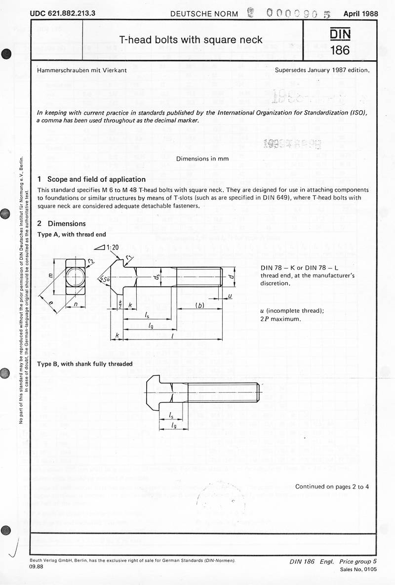

下载标准文件
DIN 186(1)
英语 · PDF · 6 页 · 15.42 MB