标准信息
STANDARD INFORMATION- 标准编号
- DIN 262-1
- 所属分类
- DIN 德国标准
- 发布机构
- DIN
- 版本年份
- 1970
- 文件语言
- 英语
- 文件格式
- 文件页数
- 6 页
- 文件大小
- 4.34 MB
中文名称为参考译名,文件语言以原文为准。
· 更新:
标准简介
OVERVIEW中文简介
该标准规定了T型头螺栓的尺寸、公差、材料要求及机械性能。适用于M8至M100规格的T型头螺栓,涵盖其几何参数、质量计算及验收检验条件。
English summary
This standard specifies the dimensions, tolerances, material requirements, and mechanical properties for T-head bolts. It applies to T-head bolts with sizes ranging from M8 to M100, covering geometric parameters, mass calculations, and acceptance inspection conditions.
以上为根据文件整理的内容简介。
相关标签
标准内容预览
DOCUMENT PREVIEWRundgewinde mit Spiel und steiler Flanke mit Steigung 7 mm Nennmaße
Round thread with clearance and steep flank with pitch 7 mm; theoretical values
Gewinde nach dieser Norm wird hauptsächlich bei Bremszugstangen, Spannschlössern und Zughaken angewendet.
Maße in mm
Mutter
Bolzen
Bezeichnung eines rechtsgängigen Rundgewindes von 59 mm Gewinde-Nenndurchmesser und 7 mm Steigung1):
Rd 59 × 7 DIN 262
Bezeichnung eines linksgängigen Rundgewindes von 59 mm Gewinde-Nenndurchmesser und 7 mm Steigung:
Rd 59 × 7 links DIN 262
| Gewinde-Nenndurchmesser | Bolzen | Mutter | |||||
|---|---|---|---|---|---|---|---|
| Außendurchmesser d | Kerndurchmesser d1 | Kernquerschnitt cm2 | Flankendurchmesser d2 | Außendurchmesser D | Kerndurchmesser D1 | Flankendurchmesser D2 | |
| 34 | 34 | 25 | 4,91 | 29,5 | 34,4 | 25,4 | 31,143 |
| 39 | 39 | 30 | 7,07 | 34,5 | 39,4 | 30,4 | 36,143 |
| 42 | 42 | 33 | 8,55 | 37,5 | 42,4 | 33,4 | 39,143 |
| 44 | 44 | 35 | 9,62 | 39,5 | 44,4 | 35,4 | 41,143 |
| 49 | 49 | 40 | 12,56 | 44,5 | 49,4 | 40,4 | 46,143 |
| 54 | 54 | 45 | 15,90 | 49,5 | 54,4 | 45,4 | 51,143 |
| 59 | 59 | 50 | 19,63 | 54,5 | 59,4 | 50,4 | 56,143 |
| 64 | 64 | 55 | 23,76 | 59,5 | 64,4 | 55,4 | 61,143 |
| 69 | 69 | 60 | 28,27 | 64,5 | 69,4 | 60,4 | 66,143 |
| 70 | 70 | 61 | 29,22 | 65,5 | 70,4 | 61,4 | 67,143 |
| 74 | 74 | 65 | 33,18 | 69,5 | 74,4 | 65,4 | 71,143 |
| 79 | 79 | 70 | 38,48 | 74,5 | 79,4 | 70,4 | 76,143 |
Sind weitere Gewinde-Nenndurchmesser unvermeidlich, so sind solche mit den Endzahlen 4 und 9 zu wählen.
1) Bei Teilen, die mit Rechts- und Linksgewinde versehen sind, ist auch in die Bezeichnung des rechtsgängigen Gewindes das Wort „rechts“ zu setzen, z. B. Rd 59 × 7 rechts DIN 262
Gewindegrenzmaße und Abmaße, zulässige Abweichungen und zulässige Abnutzungen der Gewindelehren nach DIN 262 Blatt 2.
Fachnormenausschuß Schienenfahrzeuge im Deutschen Normenausschuß (DNA)
Ausschuß Gewinde im DNA
1
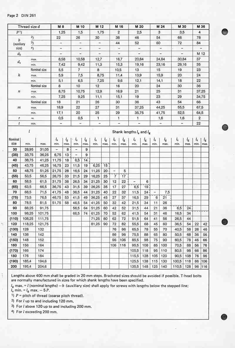
DIN 261
| Thread size d | M 8 | M 10 | M 12 | M 16 | M 20 | M 24 | M 30 | M 36 | ||||||||||
|---|---|---|---|---|---|---|---|---|---|---|---|---|---|---|---|---|---|---|
| P 1) | 1,25 | 1,5 | 1,75 | 2 | 2,5 | 3 | 3,5 | 4 | ||||||||||
| b (auxiliary size) | 22 | 26 | 30 | 38 | 46 | 54 | 66 | 78 | ||||||||||
| – | – | – | 44 | 52 | 60 | 72 | 84 | |||||||||||
| – | – | – | – | – | – | – | – | |||||||||||
| db | – | – | – | – | – | – | – | M 12 | ||||||||||
| ds | 8,58 | 10,58 | 12,7 | 16,7 | 20,84 | 24,84 | 30,84 | 37 | ||||||||||
| 7,42 | 9,42 | 11,3 | 15,3 | 19,16 | 23,16 | 29,16 | 35 | |||||||||||
| k | 5,5 | 7 | 8 | 10,5 | 13 | 15 | 19 | 23 | ||||||||||
| 5,9 | 7,5 | 8,75 | 11,4 | 13,9 | 15,9 | 20 | 24 | |||||||||||
| 5,1 | 6,5 | 7,25 | 9,6 | 12,1 | 14,1 | 18 | 22 | |||||||||||
| n | 8 | 10 | 12 | 16 | 20 | 24 | 30 | 36 | ||||||||||
| 8,75 | 10,75 | 12,9 | 16,9 | 21 | 25 | 31 | 37,25 | |||||||||||
| 7,25 | 9,25 | 11,1 | 15,1 | 19 | 23 | 29 | 34,75 | |||||||||||
| m | 18 | 21 | 26 | 30 | 36 | 43 | 54 | 66 | ||||||||||
| 18,9 | 22 | 27 | 31 | 37,25 | 44,25 | 55,5 | 67,5 | |||||||||||
| 17,1 | 20 | 25 | 29 | 35,75 | 41,75 | 52,5 | 64,5 | |||||||||||
| r ≈ | 0,5 | 0,5 | 1 | 1 | 1 | 1,6 | 1,6 | 2 | ||||||||||
| t min. | – | – | – | – | – | – | – | 22 | ||||||||||
| l | Shank lengths ls and lg | |||||||||||||||||
| Nominal size | min. | max. | ls min. | lg max. | ls min. | lg max. | ls min. | lg max. | ls min. | lg max. | ls min. | lg max. | ls min. | lg max. | ls min. | lg max. | ls min. | lg max. |
| 30 | 28,95 | 31,05 | – | 8 | – | 9 | ||||||||||||
| (35) | 33,75 | 36,25 | 6,75 | 13 | – | 9 | ||||||||||||
| 40 | 38,75 | 41,25 | 11,75 | 18 | 6,5 | 14 | ||||||||||||
| (45) | 43,75 | 46,25 | 16,75 | 23 | 11,5 | 19 | 6,25 | 15 | ||||||||||
| 50 | 48,75 | 51,25 | 21,75 | 28 | 16,5 | 24 | 11,25 | 20 | – | 5 | ||||||||
| (55) | 53,5 | 56,5 | 26,75 | 33 | 21,5 | 29 | 16,25 | 25 | 7 | 17 | ||||||||
| 60 | 58,5 | 61,5 | 31,75 | 38 | 26,5 | 34 | 21,25 | 30 | 12 | 22 | – | 6 | ||||||
| (65) | 63,5 | 66,5 | 36,75 | 43 | 31,5 | 39 | 26,25 | 35 | 17 | 27 | 6,5 | 19 | ||||||
| 70 | 68,5 | 71,5 | 41,75 | 48 | 36,5 | 44 | 31,25 | 40 | 22 | 32 | 11,5 | 24 | – | 7,5 | ||||
| (75) | 73,5 | 76,5 | 46,75 | 53 | 41,5 | 49 | 36,25 | 45 | 27 | 37 | 16,5 | 29 | 6 | 21 | ||||
| 80 | 78,5 | 81,5 | 51,75 | 58 | 46,5 | 54 | 41,25 | 50 | 32 | 42 | 21,5 | 34 | 11 | 26 | ||||
| 90 | 88,25 | 91,75 | 56,5 | 64 | 51,25 | 60 | 42 | 52 | 31,5 | 44 | 21 | 36 | 6,5 | 24 | ||||
| 100 | 98,25 | 101,75 | 66,5 | 74 | 61,25 | 70 | 52 | 62 | 41,5 | 54 | 31 | 46 | 16,5 | 34 | ||||
| (110) | 108,25 | 111,75 | 71,25 | 80 | 62 | 72 | 51,5 | 64 | 41 | 56 | 26,5 | 44 | ||||||
| 120 | 118,25 | 121,75 | 81,25 | 90 | 72 | 82 | 55,5 | 68 | 45 | 60 | 36,5 | 54 | 22 | 42 | ||||
| (130) | 128 | 132 | 76 | 86 | 65,5 | 78 | 55 | 70 | 40,5 | 58 | 26 | 46 | ||||||
| 140 | 138 | 142 | 86 | 96 | 75,5 | 88 | 65 | 80 | 50,5 | 68 | 36 | 56 | ||||||
| (150) | 148 | 152 | 96 | 106 | 85,5 | 98 | 75 | 90 | 60,5 | 78 | 46 | 66 | ||||||
| 160 | 156 | 164 | 106 | 116 | 95,5 | 108 | 85 | 100 | 70,5 | 88 | 56 | 76 | ||||||
| (170) | 166 | 174 | 105,5 | 118 | 95 | 110 | 80,5 | 98 | 66 | 86 | ||||||||
| 180 | 176 | 184 | 115,5 | 128 | 105 | 120 | 90,5 | 108 | 76 | 96 | ||||||||
| (190) | 185,4 | 194,6 | 125,5 | 138 | 115 | 130 | 100,5 | 118 | 86 | 106 | ||||||||
| 200 | 195,4 | 204,6 | 135,5 | 148 | 125 | 140 | 110,5 | 128 | 96 | 116 | ||||||||
Lengths above 400 mm shall be graded in 20 mm steps. Bracketed sizes should be avoided if possible. T-head bolts are normally manufactured in sizes for which shank lengths have been specified.
lg max. = l (nominal lengths) – b (auxiliary size) shall apply for screws with lengths below the stepped line;
ls min. = lg max. – 5 P.
1) P = pitch of thread (coarse pitch thread).
2) For l up to and including 120 mm.
3) For l above 120 up to and including 200 mm.
4) For l exceeding 200 mm.
2
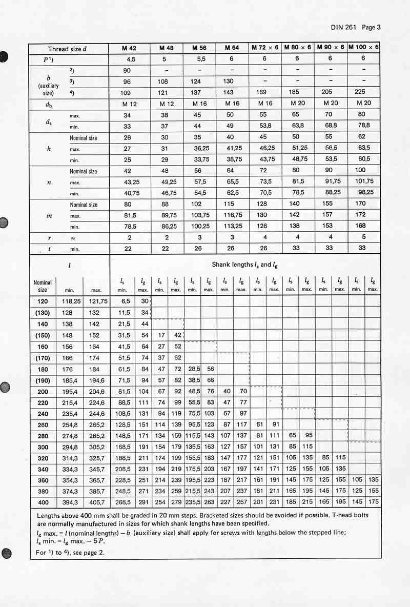
DIN 261
| Thread size d | M 42 | M 48 | M 56 | M 64 | M 72 x 6 | M 80 x 6 | M 90 x 6 | M 100 x 6 | |
|---|---|---|---|---|---|---|---|---|---|
| P 1) | 4,5 | 5 | 5,5 | 6 | 6 | 6 | 6 | 6 | |
| b (auxiliary size) | 2) | 90 | - | - | - | - | - | - | - |
| 3) | 96 | 108 | 124 | 130 | - | - | - | - | |
| 4) | 109 | 121 | 137 | 143 | 169 | 185 | 205 | 225 | |
| db | M 12 | M 12 | M 16 | M 16 | M 16 | M 20 | M 20 | M 20 | |
| ds | max. | 34 | 38 | 45 | 50 | 55 | 65 | 70 | 80 |
| min. | 33 | 37 | 44 | 49 | 53,8 | 63,8 | 68,8 | 78,8 | |
| k | Nominal size | 26 | 30 | 35 | 40 | 45 | 50 | 55 | 62 |
| max. | 27 | 31 | 36,25 | 41,25 | 46,25 | 51,25 | 56,5 | 63,5 | |
| min. | 25 | 29 | 33,75 | 38,75 | 43,75 | 48,75 | 53,5 | 60,5 | |
| n | Nominal size | 42 | 48 | 56 | 64 | 72 | 80 | 90 | 100 |
| max. | 43,25 | 49,25 | 57,5 | 65,5 | 73,5 | 81,5 | 91,75 | 101,75 | |
| min. | 40,75 | 46,75 | 54,5 | 62,5 | 70,5 | 78,5 | 88,25 | 98,25 | |
| m | Nominal size | 80 | 88 | 102 | 115 | 128 | 140 | 155 | 170 |
| max. | 81,5 | 89,75 | 103,75 | 116,75 | 130 | 142 | 157 | 172 | |
| min. | 78,5 | 86,25 | 100,25 | 113,25 | 126 | 138 | 153 | 168 | |
| r | = | 2 | 2 | 3 | 3 | 4 | 4 | 4 | 5 |
| t | min. | 22 | 22 | 26 | 26 | 26 | 33 | 33 | 33 |
| l | Shank lengths ls and lg | |||||||||||||||||||
|---|---|---|---|---|---|---|---|---|---|---|---|---|---|---|---|---|---|---|---|---|
| Nominal size | min. | max. | ls min. | lg max. | ls min. | lg max. | ls min. | lg max. | ls min. | lg max. | ls min. | lg max. | ls min. | lg max. | ls min. | lg max. | ls min. | lg max. | ||
| 120 | 118,25 | 121,75 | 6,5 | 30 | ||||||||||||||||
| (130) | 128 | 132 | 11,5 | 34 | ||||||||||||||||
| 140 | 138 | 142 | 21,5 | 44 | ||||||||||||||||
| (150) | 148 | 152 | 31,5 | 54 | 17 | 42 | ||||||||||||||
| 160 | 156 | 164 | 41,5 | 64 | 27 | 52 | ||||||||||||||
| (170) | 166 | 174 | 51,5 | 74 | 37 | 62 | ||||||||||||||
| 180 | 176 | 184 | 61,5 | 84 | 47 | 72 | 28,5 | 56 | ||||||||||||
| (190) | 185,4 | 194,6 | 71,5 | 94 | 57 | 82 | 38,5 | 66 | ||||||||||||
| 200 | 195,4 | 204,6 | 81,5 | 104 | 67 | 92 | 48,5 | 76 | 40 | 70 | ||||||||||
| 220 | 215,4 | 224,6 | 88,5 | 111 | 74 | 99 | 55,5 | 83 | 47 | 77 | ||||||||||
| 240 | 235,4 | 244,6 | 108,5 | 131 | 94 | 119 | 75,5 | 103 | 67 | 97 | ||||||||||
| 260 | 254,8 | 265,2 | 128,5 | 151 | 114 | 139 | 95,5 | 123 | 87 | 117 | 61 | 91 | ||||||||
| 280 | 274,8 | 285,2 | 148,5 | 171 | 134 | 159 | 115,5 | 143 | 107 | 137 | 81 | 111 | 65 | 95 | ||||||
| 300 | 294,8 | 305,2 | 168,5 | 191 | 154 | 179 | 135,5 | 163 | 127 | 157 | 101 | 131 | 85 | 115 | ||||||
| 320 | 314,3 | 325,7 | 188,5 | 211 | 174 | 199 | 155,5 | 183 | 147 | 177 | 121 | 151 | 105 | 135 | 85 | 115 | ||||
| 340 | 334,3 | 345,7 | 208,5 | 231 | 194 | 219 | 175,5 | 203 | 167 | 197 | 141 | 171 | 125 | 155 | 105 | 135 | ||||
| 360 | 354,3 | 365,7 | 228,5 | 251 | 214 | 239 | 195,5 | 223 | 187 | 217 | 161 | 191 | 145 | 175 | 125 | 155 | 105 | 135 | ||
| 380 | 374,3 | 385,7 | 248,5 | 271 | 234 | 259 | 215,5 | 243 | 207 | 237 | 181 | 211 | 165 | 195 | 145 | 175 | 125 | 155 | ||
| 400 | 394,3 | 405,7 | 268,5 | 291 | 254 | 279 | 235,5 | 263 | 227 | 257 | 201 | 231 | 185 | 215 | 165 | 195 | 145 | 175 | ||
Lengths above 400 mm shall be graded in 20 mm steps. Bracketed sizes should be avoided if possible. T-head bolts are normally manufactured in sizes for which shank lengths have been specified.
lg max. = l (nominal lengths) - b (auxiliary size) shall apply for screws with lengths below the stepped line;
ls min. = lg max. - 5 P.
For 1) to 4), see page 2.
3
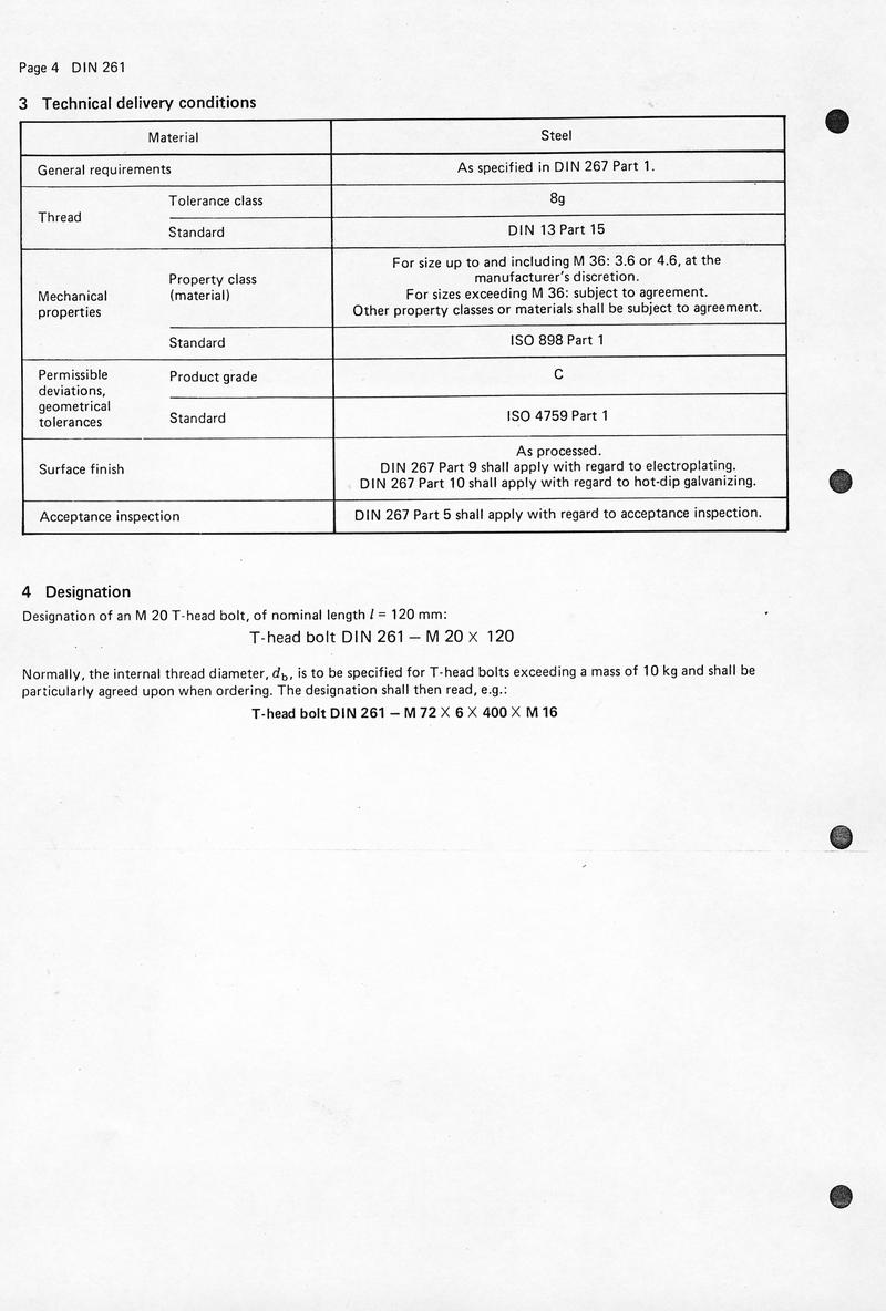
3 Technical delivery conditions
| Material | Steel | |
|---|---|---|
| General requirements | As specified in DIN 267 Part 1. | |
| Thread | Tolerance class | 8g |
| Standard | DIN 13 Part 15 | |
| Mechanical properties | Property class (material) | For size up to and including M 36: 3.6 or 4.6, at the manufacturer's discretion. For sizes exceeding M 36: subject to agreement. Other property classes or materials shall be subject to agreement. |
| Standard | ISO 898 Part 1 | |
| Permissible deviations, geometrical tolerances | Product grade | C |
| Standard | ISO 4759 Part 1 | |
| Surface finish | As processed. DIN 267 Part 9 shall apply with regard to electroplating. DIN 267 Part 10 shall apply with regard to hot-dip galvanizing. | |
| Acceptance inspection | DIN 267 Part 5 shall apply with regard to acceptance inspection. | |
4 Designation
Designation of an M 20 T-head bolt, of nominal length l = 120 mm:
T-head bolt DIN 261 — M 20 × 120
Normally, the internal thread diameter, db, is to be specified for T-head bolts exceeding a mass of 10 kg and shall be particularly agreed upon when ordering. The designation shall then read, e.g.:
T-head bolt DIN 261 — M 72 × 6 × 400 × M 16
4
5 Masses
| Thread size d | M 8 | M 10 | M 12 | M 16 | M 20 | M 24 | M 30 | M 36 |
|---|---|---|---|---|---|---|---|---|
| l | Mass (7,85 kg/dm3), in kg per 1000 units, approximately | |||||||
| 30 | 18,0 | 28,2 | ||||||
| (35) | 19,5 | 31,3 | ||||||
| 40 | 20,0 | 34,4 | ||||||
| (45) | 22,0 | 37,5 | 56,5 | |||||
| 50 | 23,9 | 40,6 | 60,9 | 113 | ||||
| (55) | 25,9 | 43,7 | 65,4 | 121 | ||||
| 60 | 27,9 | 46,8 | 69,8 | 129 | 211 | |||
| (65) | 29,8 | 49,9 | 74,3 | 137 | 223 | |||
| 70 | 31,8 | 53,0 | 78,7 | 145 | 236 | 355 | ||
| (75) | 33,8 | 56,1 | 83,1 | 153 | 248 | 373 | ||
| 80 | 37,7 | 59,2 | 87,6 | 161 | 260 | 390 | ||
| 90 | 65,4 | 96,5 | 176 | 285 | 426 | |||
| 100 | 71,6 | 105 | 192 | 310 | 461 | 812 | ||
| (110) | 114 | 208 | 334 | 497 | 868 | |||
| 120 | 123 | 224 | 359 | 532 | 923 | 1310 | ||
| (130) | 239 | 384 | 568 | 978 | 1390 | |||
| 140 | 255 | 408 | 603 | 1030 | 1470 | |||
| (150) | 271 | 433 | 639 | 1090 | 1550 | |||
| 160 | 287 | 458 | 674 | 1140 | 1630 | |||
| (170) | 483 | 710 | 1200 | 1710 | ||||
| 180 | 507 | 745 | 1260 | 1790 | ||||
| (190) | 532 | 781 | 1310 | 1870 | ||||
| 200 | 557 | 816 | 1370 | 1950 | ||||
| Thread size d | M 42 | M 48 | M 56 | M 64 | M 72 × 6 | M 80 × 6 | M 90 × 6 | M 100 × 6 |
|---|---|---|---|---|---|---|---|---|
| l | Mass (7,85 kg/dm3), in kg per 1000 units, approximately | |||||||
| 120 | 1800 | |||||||
| (130) | 1870 | |||||||
| 140 | 1940 | |||||||
| (150) | 2010 | 2770 | ||||||
| 160 | 2080 | 2860 | ||||||
| (170) | 2150 | 2950 | ||||||
| 180 | 2220 | 3040 | 4310 | |||||
| (190) | 2290 | 3130 | 4440 | |||||
| 200 | 2360 | 3220 | 4560 | 6290 | ||||
| 220 | 2510 | 3400 | 4800 | 6600 | ||||
| 240 | 2650 | 3570 | 5060 | 6910 | ||||
| 260 | 2790 | 3750 | 5310 | 7220 | 9530 | |||
| 280 | 2930 | 3930 | 5560 | 7530 | 9900 | |||
| 300 | 3080 | 4110 | 5810 | 7840 | 10300 | 13600 | ||
| 320 | 3220 | 4290 | 6060 | 8150 | 10600 | 14200 | ||
| 340 | 3360 | 4460 | 6310 | 8460 | 11000 | 14700 | 18500 | |
| 360 | 3500 | 4640 | 6560 | 8770 | 11400 | 15200 | 19100 | 24500 |
| 380 | 3640 | 4820 | 6810 | 9080 | 11800 | 15700 | 19700 | 25300 |
| 400 | 3780 | 5000 | 7060 | 9390 | 12300 | 16200 | 20300 | 26100 |
The values of mass specified are for guidance only and cover the commercial sizes.
5
Standards referred to
| DIN 13 Part 15 | ISO metric screw threads; fundamental deviations and tolerances for screw threads of 1 mm and larger |
| DIN 78 | Thread ends; lengths of projection of thread ends for ISO metric screw threads as defined in DIN 13 |
| DIN 267 Part 1 | Fasteners; technical delivery conditions; general requirements |
| DIN 267 Part 5 | Fasteners; technical delivery conditions; acceptance inspection (modified version of ISO 3269, 1984 edition) |
| DIN 267 Part 9 | Fasteners; technical delivery conditions; components with electroplated coatings |
| DIN 267 Part 10 | Fasteners; technical delivery conditions; hot-dip galvanized components |
| DIN 649 | T-slots for T-head bolts |
| ISO 898 Part 1 | Mechanical properties of fasteners; bolts, screws and studs |
| ISO 4759 Part 1 | Tolerances for fasteners; bolts, screws and nuts with thread diameters between 1,6 (inclusive) and 150 mm (inclusive) and product grades A, B and C |
Previous editions
DIN 261: 06.23, 04.27, 07.36, 12.70.
DIN 261 Part 1: 01.42, 08.53, 03.63.
Amendments
The following amendments have been made in comparison with the January 1970 edition.
a) The previous design g as specified in DIN 267 Part 2 has been replaced by product grade C as specified in ISO 4759 Part 1.
b) The technical delivery conditions have been amended and harmonized with the relevant basic standards.
c) The limits of size calculated from the permissible deviations have been included.
d) The shank lengths, ls and lg, have been included.
e) The standard has been editorially revised.
International Patent Classification
F 16 B 35/04
6
预览内容由文件识别整理,表格、公式及文字请以原始文件为准。
原文图片预览
PAGE IMAGES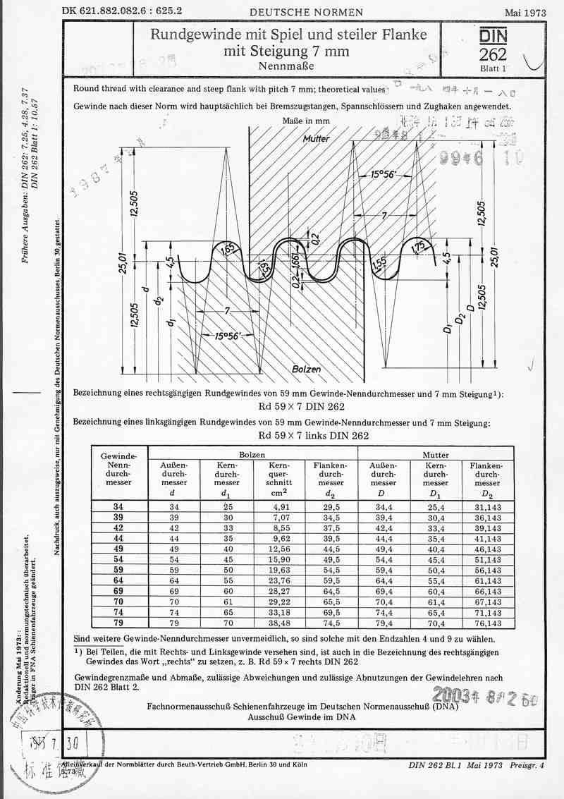
下载标准文件
DIN 262-1
英语 · PDF · 6 页 · 4.34 MB