AASHTO公路与城市道路几何设计规范(2011版)——勘误
AASHTO公路与城市道路几何设计规范(2011版)——勘误
AASHTO公路与城市道路几何设计规范(2011版)——勘误
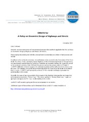
标准信息
STANDARD INFORMATION- 标准编号
- AASHTO公路与城市道路几何设计规范(2011版)——勘误
- 所属分类
- AASHTO 美国公路与运输标准
- 文件语言
- 英语
- 文件格式
- 文件页数
- 6 页
- 文件大小
- 797.95 KB
· 更新:
标准简介
OVERVIEW中文简介
标准 AASHTO公路与城市道路几何设计规范(2011版)——勘误 的预览内容
English summary
Preview of standard AASHTO公路与城市道路几何设计规范(2011版)——勘误
以上为根据文件整理的内容简介。
标准内容预览
DOCUMENT PREVIEWFigure 2-4. Minimum Turning Path for Intercity Bus (BUS-12 [BUS-40]) Design Vehicle
- Max. steering angle is 41.8°
- CTR = Centerline turning radius at front axle
6
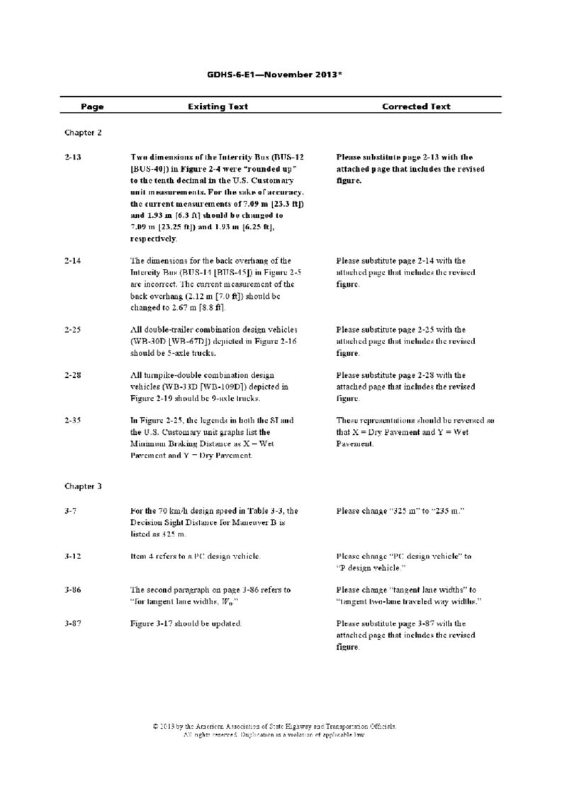
GDHS-6-E1—November 2013*
| Page | Existing Text | Corrected Text |
|---|---|---|
| Chapter 2 | ||
| 2-13 | Two dimensions of the InterCity Bus (BUS-12 [BUS-40]) in Figure 2-4 were "rounded up" to the tenth decimal in the U.S. Customary unit measurements. For the sake of accuracy, the current measurements of 7.49 m [23.3 ft] and 1.93 m [6.3 ft] should be changed to 7.09 m [23.25 ft] and 1.93 m [6.25 ft], respectively. | Please substitute page 2-13 with the attached page that includes the revised figure. |
| 2-14 | The dimensions for the back overhang of the InterCity Bus (BUS-14 [BUS-45]) in Figure 2-5 are incorrect. The current measurement of the back overhang (2.12 m [7.0 ft]) should be changed to 2.67 m [8.8 ft]. | Please substitute page 2-14 with the attached page that includes the revised figure. |
| 2-25 | All double-trailer combination design vehicles (WB-30D [WB-67D]) depicted in Figure 2-16 should be 5-axle trucks. | Please substitute page 2-25 with the attached page that includes the revised figure. |
| 2-28 | All turnpike-double combination design vehicles (WB-33D [WB-109D]) depicted in Figure 2-19 should be 9-axle trucks. | Please substitute page 2-28 with the attached page that includes the revised figure. |
| 2-35 | In Figure 2-25, the legends in both the SI and the U.S. Customary unit graphs list the Minimum Braking Distance as X = Wet Pavement and Y = Dry Pavement. | These representations should be reversed so that X = Dry Pavement and Y = Wet Pavement. |
| Chapter 3 | ||
| 3-7 | For the 70 km/h design speed in Table 3-3, the Decision Sight Distance for Maneuver B is listed as 325 m. | Please change "325 m" to "235 m." |
| 3-12 | Item 4 refers to a PC design vehicle. | Please change "PC design vehicle" to "P design vehicle." |
| 3-86 | The second paragraph on page 3-86 refers to "for tangent lane widths, Wn" | Please change "tangent lane widths" to "tangent two-lane traveled way widths." |
| 3-87 | Figure 3-17 should be updated. | Please substitute page 3-87 with the attached page that includes the revised figure. |
2
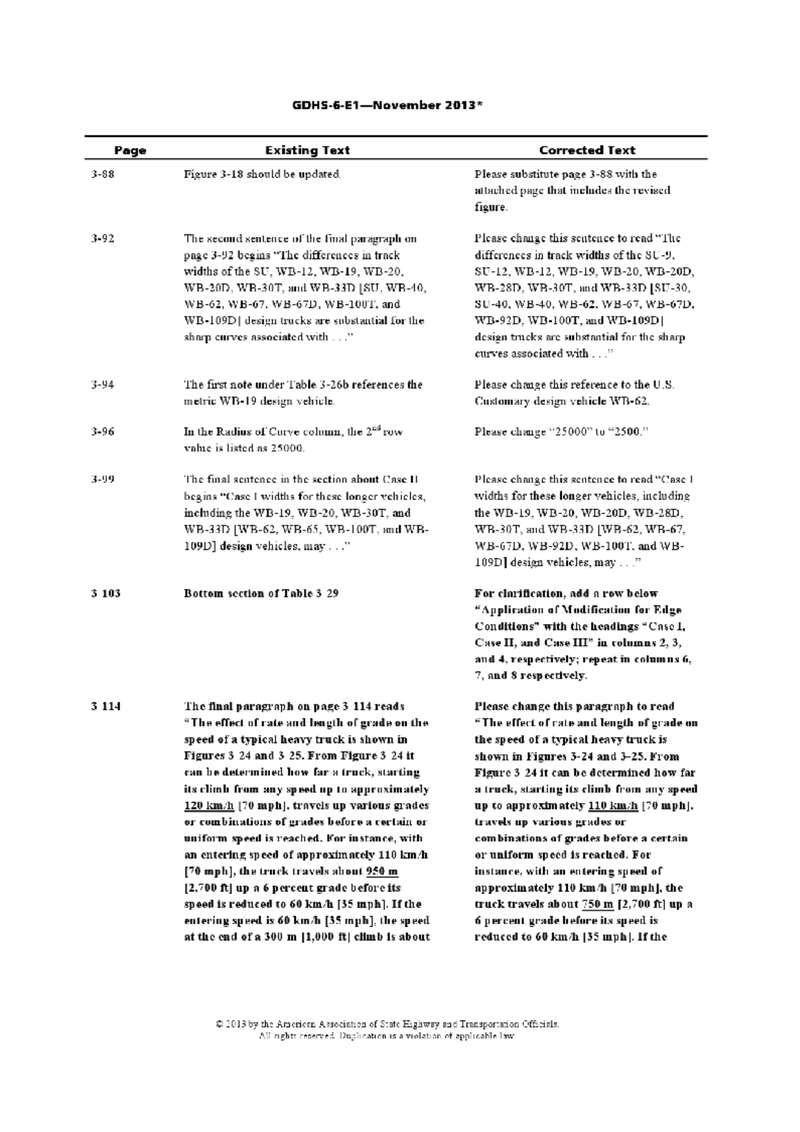
GDHS-6-E1—November 2013*
| Page | Existing Text | Corrected Text |
|---|---|---|
| 3-88 | Figure 3-18 should be updated. | Please substitute page 3-88 with the attached page that includes the revised figure. |
| 3-92 | The second sentence of the final paragraph on page 3-92 begins "The differences in track widths of the SU, WB-12, WB-19, WB-20, WB-20D, WB-30T, and WB-33D [SU, WB-40, WB-62, WB-67, WB-67D, WB-100T, and WB-109D] design trucks are substantial for the sharp curves associated with . . ." | Please change this sentence to read "The differences in track widths of the SU-9, SU-12, WB-12, WB-19, WB-20, WB-20D, WB-28D, WB-30T, and WB-33D [SU-30, SU-40, WB-40, WB-62, WB-67, WB-67D, WB-92D, WB-100T, and WB-109D] design trucks are substantial for the sharp curves associated with . . ." |
| 3-94 | The first note under Table 3-26b references the metric WB-19 design vehicle. | Please change this reference to the U.S. Customary design vehicle WB-62. |
| 3-96 | In the Radius of Curve column, the 2nd row value is listed as 25000. | Please change "25000" to "2500." |
| 3-99 | The final sentence in the section about Case II begins "Case I widths for these longer vehicles, including the WB-19, WB-20, WB-20D, WB-30T, and WB-33D [WB-62, WB-65, WB-100T, and WB-109D] design vehicles, may . . ." | Please change this sentence to read "Case I widths for these longer vehicles, including the WB-19, WB-20, WB-20D, WB-28D, WB-30T, and WB-33D [WB-62, WB-67, WB-67D, WB-92D, WB-100T, and WB-109D] design vehicles, may . . ." |
| 3-103 | Bottom section of Table 3-29 | For clarification, add a row below "Application of Modification for Edge Conditions" with the headings "Case I, Case II, and Case III" in columns 2, 3, and 4, respectively; repeat in columns 6, 7, and 8 respectively. |
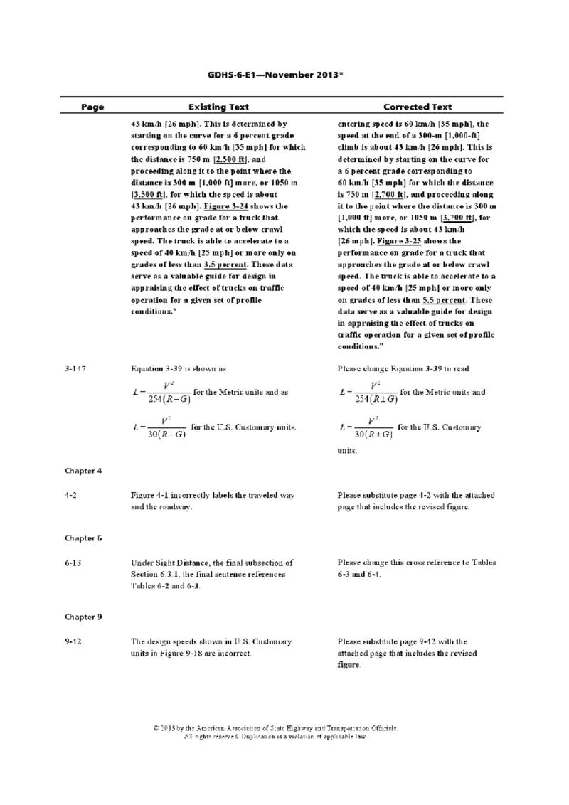
GDHS-6-E1—November 2013*
| Page | Existing Text | Corrected Text |
|---|---|---|
|
43 km/h [26 mph]. This is determined by starting on the curve for a 6 percent grade corresponding to 60 km/h [35 mph] for which the distance is 750 m [2,500 ft], and proceeding along it to the point where the distance is 300 m [1,000 ft] more, or 1050 m [3,500 ft], for which the speed is about 43 km/h [26 mph]. Figure 3-24 shows the performance on grade for a truck that approaches the grade at or below crawl speed. The truck is able to accelerate to a speed of 40 km/h [25 mph] or more only on grades of less than 3.5 percent. These data serve as a valuable guide for design in appraising the effect of trucks on traffic operation for a given set of profile conditions.” |
entering speed is 60 km/h [35 mph], the speed at the end of a 300-m [1,000-ft] climb is about 43 km/h [26 mph]. This is determined by starting on the curve for a 6 percent grade corresponding to 60 km/h [35 mph] for which the distance is 750 m [2,700 ft], and proceeding along it to the point where the distance is 300 m [1,000 ft] more, or 1050 m [3,700 ft], for which the speed is about 43 km/h [26 mph]. Figure 3-25 shows the performance on grade for a truck that approaches the grade at or below crawl speed. The truck is able to accelerate to a speed of 40 km/h [25 mph] or more only on grades of less than 5.5 percent. These data serve as a valuable guide for design in appraising the effect of trucks on traffic operation for a given set of profile conditions.” |
|
| 3-147 |
Equation 3-39 is shown as L = V2 / [254(R ± G)] for the Metric units and as L = V2 / [30(R ± G)] for the U.S. Customary units. |
Please change Equation 3-39 to read L = V2 / [254(R ± G)] for the Metric units and L = V2 / [30(R ± G)] for the U.S. Customary units. |
| Chapter 4 | ||
| 4-2 |
Figure 4-1 incorrectly labels the traveled way and the roadway. |
Please substitute page 4-2 with the attached page that includes the revised figure. |
| Chapter 5 | ||
| 6-13 |
Under Sight Distance, the final subsection of Section 6.3.1, the final sentence references Tables 6-2 and 6-4. |
Please change this cross reference to Tables 6-3 and 6-4. |
| Chapter 9 | ||
| 9-12 |
The design speeds shown in U.S. Customary units in Figure 9-18 are incorrect. |
Please substitute page 9-12 with the attached page that includes the revised figure. |
4
GDHS-6-E1—November 2013*
| Page | Existing Text | Corrected Text |
|---|---|---|
| 9-45 | In the 7th row of Table 9-9 under U.S. Customary units, the Design Speed is listed as 4. | Please change this Design Speed to 45. |
| 9-74 | The dimensions for Diagram B in Figure 9-28 (Metric) are incorrect. | Please substitute page 9-74 with the attached page that includes the revised figure. |
| 9-75 | The dimensions for Diagram B in Figure 9-28 (U.S. Customary) are incorrect. | Please substitute page 9-75 with the attached page that includes the revised figure. |
| Chapter 10 | ||
| 10-78 | In Figure 10-53, Part D2 incorrectly cross references Figure 10-69. | Please change the cross reference to “For Deceleration Length See Table 10-5.” |
| 10-93 | Item 1 under Superelevation and cross slope refers to Figures 3-21 through 3-25. Item 3 refers to Figures 3-29 and 3-30. | The correct cross reference should be “Tables 3-8 through 3-12.” Please change these cross references to Tables 3-15 and 3-16, respectively. |
| 10-108 | Note 2 in Figure 10-69 states, “Point A controls speed on the ramp. Ls should not start back on the curvature of the ramp unless the radius equals 300 m [100 ft] or more.” | Please change “100 ft” to “1,000 ft.” |
* Items shown in bold are recent additions to the 2012 edition of the GDHS-6 errata.
5
Figure 2-4. Minimum Turning Path for Intercity Bus (BUS-12 [BUS-40]) Design Vehicle
- Max. steering angle is 41.8°
- CTR = Centerline turning radius at front axle
6
预览内容由文件识别整理,表格、公式及文字请以原始文件为准。
原文图片预览
PAGE IMAGES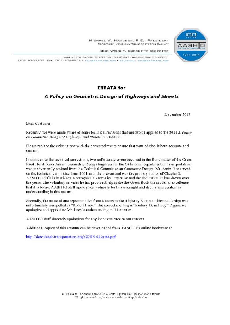
下载标准文件
AASHTO公路与城市道路几何设计规范(2011版)——勘误
英语 · PDF · 6 页 · 797.95 KB