AASHTO T106-02(ASTM C109-109M-99)
AASHTO T106-02(ASTM C109-109M-99)
AASHTO T106-02(ASTM C109-109M-99)

标准信息
STANDARD INFORMATION- 标准编号
- AASHTO T106-02(ASTM C109-109M-99)
- 所属分类
- AASHTO 美国公路与运输标准
- 文件语言
- 英语
- 文件格式
- 文件页数
- 6 页
- 文件大小
- 191.64 KB
· 更新:
标准简介
OVERVIEW中文简介
标准 AASHTO T106-02(ASTM C109-109M-99) 的预览内容
English summary
Preview of standard AASHTO T106-02(ASTM C109-109M-99)
以上为根据文件整理的内容简介。
标准内容预览
DOCUMENT PREVIEWTable 2—Mixing Proportions for 2-in. Cubes
| No. of Specimens | ||
|---|---|---|
| 6 | 9 | |
| Cement, g | 500 | 740 |
| Sand, g | 1375 | 2035 |
| Water, mL. | ||
| Portland (0.485) | 242 | 359 |
| Air-entraining portland (0.460) | 230 | 340 |
| Other (to flow of 110 ± 5) | — | — |
10.2. Preparation of Mortar:
10.2.1. Mechanically mix in accordance with the procedure given in T 162.
10.3. Determination of Flow:
10.3.1. Carefully wipe the flow-table top clean and dry, and place the flow mold at the center. Place a layer of mortar about 25 mm (1 in.) in thickness in the mold and tamp 20 times with the tamper. The tamping pressure shall be just sufficient to ensure uniform filling of the mold. Then fill the mold with mortar and tamp as specified for the first layer. Cut off the mortar to a plane surface, flush with the top of the mold, by drawing the straight edge of a trowel (held nearly perpendicular to the mold) with a sawing motion across the top of the mold. Wipe the table top clean and dry, being especially careful to remove any water from around the edge of the flow mold. Lift the mold away from the mortar 60 seconds after completing the mixing operation. Immediately, drop the table through a height of 13 mm (1/2 in.) 25 times in 15 seconds. Using the calipers, determine the flow by measuring the diameters of the mortar along the lines scribed in the table top, adding the four readings. The total of the four readings from the calipers equals the percent increase of the original diameter of the mortar.
10.3.2. For portland and air-entraining portland cements, merely record the flow.
10.3.3. In the case of cements other than portland or air-entraining cements, make trial mortars with varying percentages of water until the specified flow is obtained. Make each trial with fresh mortar.
10.4. Molding Test Specimens:
10.4.1. Immediately following completion of the flow test, return the mortar from the flow table to the mixing bowl. Quickly scrape the bowl sides and transfer into the batch the mortar that may have collected on the side of the bowl and then remix the entire batch 15 seconds at medium speed. Upon completion of mixing the mixing paddle shall be shaken to remove excess mortar into the mixing bowl.
10.4.2. When a duplicate batch is to be made immediately for additional specimens, the flow test may be omitted and the mortar allowed to stand in the mixing bowl 90 seconds without covering. During the last 15 seconds of this interval, quickly scrape the bowl sides and transfer into the batch the mortar that may have collected on the side of the bowl. Then remix for 15 seconds at medium speed.
6
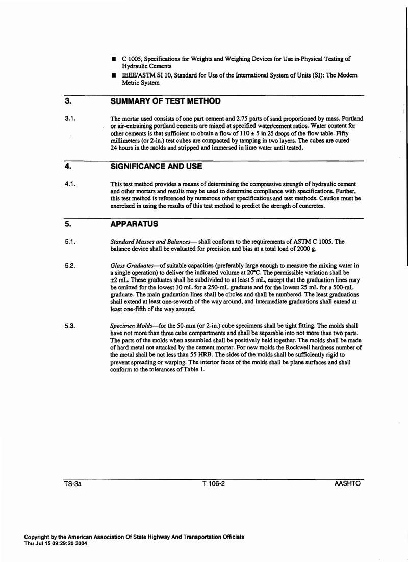
- C 1005, Specifications for Weights and Weighing Devices for Use in Physical Testing of Hydraulic Cements
- IEEE/ASTM SI 10, Standard for Use of the International System of Units (SI): The Modern Metric System
| 3. | SUMMARY OF TEST METHOD |
| 3.1. | The mortar used consists of one part cement and 2.75 parts of sand proportioned by mass. Portland or air-entraining portland cements are mixed at specified water/cement ratios. Water content for other cements is that sufficient to obtain a flow of 110 ± 5 in 25 drops of the flow table. Fifty millimeters (or 2-in.) test cubes are compacted by tamping in two layers. The cubes are cured 24 hours in the molds and stripped and immersed in lime water until tested. |
| 4. | SIGNIFICANCE AND USE |
| 4.1. | This test method provides a means of determining the compressive strength of hydraulic cement and other mortars and results may be used to determine compliance with specifications. Further, this test method is referenced by numerous other specifications and test methods. Caution must be exercised in using the results of this test method to predict the strength of concretes. |
| 5. | APPARATUS |
| 5.1. | Standard Masses and Balances—shall conform to the requirements of ASTM C 1005. The balance device shall be evaluated for precision and bias at a total load of 2000 g. |
| 5.2. | Glass Graduates—of suitable capacities (preferably large enough to measure the mixing water in a single operation) to deliver the indicated volume at 20°C. The permissible variation shall be ±2 mL. These graduates shall be subdivided to at least 5 mL, except that the graduation lines may be omitted for the lowest 10 mL for a 250-mL graduate and for the lowest 25 mL for a 500-mL graduate. The main graduation lines shall be circles and shall be numbered. The least graduations shall extend at least one-seventh of the way around, and intermediate graduations shall extend at least one-fifth of the way around. |
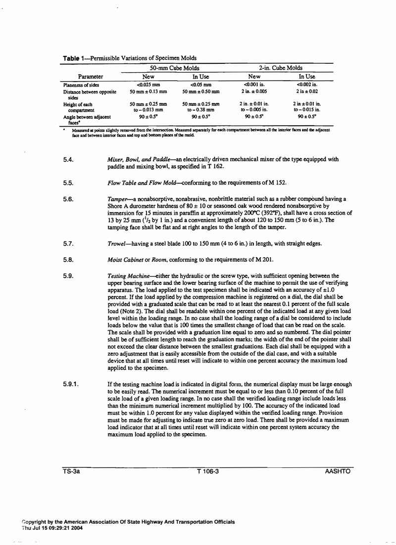
| 5.3. | Specimen Molds—for the 50-mm (or 2-in.) cube specimens shall be tight fitting. The molds shall have not more than three cube compartments and shall be separable into not more than two parts. The parts of the molds when assembled shall be positively held together. The molds shall be made of hard metal not attacked by the cement mortar. For new molds the Rockwell hardness number of the metal shall be not less than 55 HRB. The sides of the molds shall be sufficiently rigid to prevent spreading or warping. The interior faces of the molds shall be plane surfaces and shall conform to the tolerances of Table 1. |
2
Table 1—Permissible Variations of Specimen Molds
| Parameter | 50-mm Cube Molds | 2-in. Cube Molds | ||
|---|---|---|---|---|
| New | In Use | New | In Use | |
| Planelness of sides | <0.025 mm | <0.05 mm | <0.001 in. | <0.002 in. |
| Distance between opposite sides | 50 mm ± 0.13 mm | 50 mm ± 0.50 mm | 2 in. ± 0.005 | 2 in ± 0.02 |
| Height of each compartment | 50 mm ± 0.25 mm to - 0.013 mm | 50 mm ± 0.25 mm to - 0.38 mm | 2 in. ± 0.01 in. to - 0.005 in. | 2 in ± 0.01 in. to - 0.015 in. |
| Angle between adjacent faces* | 90 ± 0.5° | 90 ± 0.5° | 90 ± 0.5° | 90 ± 0.5° |
* Measured at points slightly removed from the intersection. Measured separately for each compartment between all the interior faces and the adjacent face and between interior faces and top and bottom planes of the mold.
5.4. Mixer, Bowl, and Paddle—an electrically driven mechanical mixer of the type equipped with paddle and mixing bowl, as specified in T 162.
5.5. Flow Table and Flow Mold—conforming to the requirements of M 152.
5.6. Tamper—a nonabsorptive, nonbrittle material such as a rubber compound having a Shore A durometer hardness of 80 ± 10 or seasoned oak wood rendered nonabsorptive by immersion for 15 minutes in paraffin at approximately 200°C (392°F), shall have a cross section of 13 by 25 mm (1/2 by 1 in.) and a convenient length of about 120 to 150 mm (5 to 6 in.). The tamping face shall be flat and at right angles to the length of the tamper.
5.7. Trowel—having a steel blade 100 to 150 mm (4 to 6 in.) in length, with straight edges.
5.8. Moist Cabinet or Room, conforming to the requirements of M 201.
5.9. Testing Machine—either the hydraulic or the screw type, with sufficient opening between the upper bearing surface and the lower bearing surface of the machine to permit the use of verifying apparatus. The load applied to the test specimen shall be indicated with an accuracy of ±1.0 percent. If the load applied by the compression machine is registered on a dial, the dial shall be provided with a graduated scale that can be read to at least the nearest 0.1 percent of the full scale load (Note 2). The dial shall be readable within one percent of the indicated load at any given load level within the loading range. In no case shall the loading range of a dial be considered to include loads below the value that is 100 times the smallest change of load that can be read on the scale. The scale shall be provided with a graduation line equal to zero and so numbered. The dial pointer shall be of sufficient length to reach the graduation marks; the width of the end of the pointer shall not exceed the clear distance between the smallest graduations. Each dial shall be equipped with a zero adjustment that is easily accessible from the outside of the dial case, and with a suitable device that at all times until reset will indicate to within one percent accuracy the maximum load applied to the specimen.
5.9.1. If the testing machine load is indicated in digital form, the numerical display must be large enough to be easily read. The numerical increment must be equal to or less than 0.10 percent of the full scale load of a given loading range. In no case shall the verified loading range include loads less than the minimum numerical increment multiplied by 100. The accuracy of the indicated load must be within 1.0 percent for any value displayed within the verified loading range. Provision must be made for adjusting to indicate true zero at zero load. There shall be provided a maximum load indicator that at all times until reset will indicate within one percent system accuracy the maximum load applied to the specimen.
3
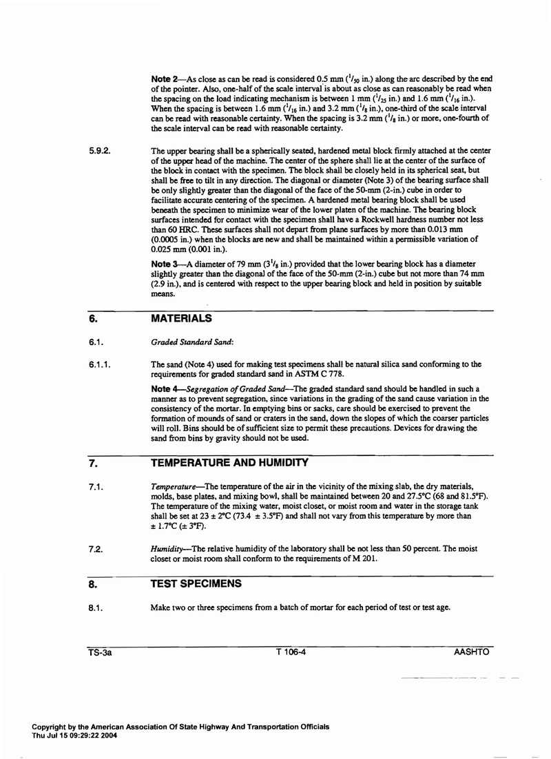
5.9.2
Note 2—As close as can be read is considered 0.5 mm (1/50 in.) along the arc described by the end of the pointer. Also, one-half of the scale interval is about as close as can reasonably be read when the spacing on the load indicating mechanism is between 1 mm (1/25 in.) and 1.6 mm (1/16 in.). When the spacing is between 1.6 mm (1/16 in.) and 3.2 mm (1/8 in.), one-third of the scale interval can be read with reasonable certainty. When the spacing is 3.2 mm (1/8 in.) or more, one-fourth of the scale interval can be read with reasonable certainty.
The upper bearing shall be a spherically seated, hardened metal block firmly attached at the center of the upper head of the machine. The center of the sphere shall lie at the center of the surface of the block in contact with the specimen. The block shall be closely held in its spherical seat, but shall be free to tilt in any direction. The diagonal or diameter (Note 3) of the bearing surface shall be only slightly greater than the diagonal of the face of the 50-mm (2-in.) cube in order to facilitate accurate centering of the specimen. A hardened metal bearing block shall be used beneath the specimen to minimize wear of the lower platen of the machine. The bearing block surfaces intended for contact with the specimen shall have a Rockwell hardness number not less than 60 HRC. These surfaces shall not depart from plane surfaces by more than 0.013 mm (0.0005 in.) when the blocks are new and shall be maintained within a permissible variation of 0.025 mm (0.001 in.).
Note 3—A diameter of 79 mm (3 1/8 in.) provided that the lower bearing block has a diameter slightly greater than the diagonal of the face of the 50-mm (2-in.) cube but not more than 74 mm (2.9 in.), and is centered with respect to the upper bearing block and held in position by suitable means.
6. MATERIALS
6.1. Graded Standard Sand:
6.1.1. The sand (Note 4) used for making test specimens shall be natural silica sand conforming to the requirements for graded standard sand in ASTM C 778.
Note 4—Segregation of Graded Sand—The graded standard sand should be handled in such a manner as to prevent segregation, since variations in the grading of the sand cause variation in the consistency of the mortar. In emptying bins or sacks, care should be exercised to prevent the formation of mounds of sand or craters in the sand, down the slopes of which the coarser particles will roll. Bins should be of sufficient size to permit these precautions. Devices for drawing the sand from bins by gravity should not be used.
7. TEMPERATURE AND HUMIDITY
7.1. Temperature—The temperature of the air in the vicinity of the mixing slab, the dry materials, molds, base plates, and mixing bowl, shall be maintained between 20 and 27.5°C (68 and 81.5°F). The temperature of the mixing water, moist closet, or moist room and water in the storage tank shall be set at 23 ± 2°C (73.4 ± 3.5°F) and shall not vary from this temperature by more than ± 1.7°C (± 3°F).
7.2. Humidity—The relative humidity of the laboratory shall be not less than 50 percent. The moist closet or moist room shall conform to the requirements of M 201.
8. TEST SPECIMENS
8.1. Make two or three specimens from a batch of mortar for each period of test or test age.
4
9. PREPARATION OF SPECIMEN MOLDS
9.1. Apply a thin coating of release agent to the interior faces of the mold and non-absorptive base plates. Apply oils and greases using an impregnated cloth or other suitable means. Wipe the mold faces and the base plate with a cloth as necessary to remove any excess release agent and to achieve a thin, even coating on the interior surfaces. When using an aerosol lubricant, spray the release agent directly onto the mold faces and base plate from a distance of 150 to 200 mm (6 to 8 in.) to achieve complete coverage. After spraying, wipe the surface with a cloth as necessary to remove any excess aerosol lubricant. The residue coating should be just sufficient to allow a distinct fingerprint to remain following light finger pressure (Note 5).
9.2. Seal the surfaces where the halves of the mold join by applying a coating of light cup grease such as petrolatum. The amount should be sufficient to extrude slightly when the two halves are tightened together. Remove any excess grease with a cloth.
9.3. After placing the mold on its base plate (and attaching, if clamp-type) carefully remove with a dry cloth any excess oil or grease from the surface of the mold and the base plate to which watertight sealant is to be applied. As a sealant, use paraffin, microcrystalline wax, or a mixture of three parts paraffin to five parts rosin by mass. Liquefy the sealant by heating between 110 and 120°C (230 and 248°F). Effect a watertight seal by applying the liquefied sealant at the outside contact lines between the mold and its base plate.
Note 5—Because aerosol lubricants evaporate, molds should be checked for a sufficient coating of lubricant immediately prior to use. If an extended period of time has elapsed since treatment, retreatment may be necessary.
Note 6—Watertight Molds—The mixture of paraffin and rosin specified for sealing the joints between molds and base plates may be found difficult to remove when molds are being cleaned. Use of straight paraffin is permissible if a watertight joint is secured; but due to the low strength of paraffin it should be used only when the mold is not held to the base plate by paraffin alone. A watertight joint may be secured with paraffin alone by slightly warming the mold and base plate before brushing the joint. Molds so treated should be allowed to return to the specified temperature before use.
10. PROCEDURE
10.1. Composition of Mortars:
10.1.1. The proportions of materials for the standard mortar shall be one part of cement to 2.75 parts of graded standard sand by mass. Use a water–cement ratio of 0.485 for all portland cements and 0.460 for all air-entraining portland cements. The amount of mixing water for other than portland and air-entraining portland cements shall be such as to produce a flow of 110 ± 5 as determined in accordance with Section 10.3 and shall be expressed as mass percent of cement.
10.1.2. The quantities of materials to be mixed at one time in the batch of mortar for making six and nine test specimens shall be as follows in Table 2:
5
Table 2—Mixing Proportions for 2-in. Cubes
| No. of Specimens | ||
|---|---|---|
| 6 | 9 | |
| Cement, g | 500 | 740 |
| Sand, g | 1375 | 2035 |
| Water, mL. | ||
| Portland (0.485) | 242 | 359 |
| Air-entraining portland (0.460) | 230 | 340 |
| Other (to flow of 110 ± 5) | — | — |
10.2. Preparation of Mortar:
10.2.1. Mechanically mix in accordance with the procedure given in T 162.
10.3. Determination of Flow:
10.3.1. Carefully wipe the flow-table top clean and dry, and place the flow mold at the center. Place a layer of mortar about 25 mm (1 in.) in thickness in the mold and tamp 20 times with the tamper. The tamping pressure shall be just sufficient to ensure uniform filling of the mold. Then fill the mold with mortar and tamp as specified for the first layer. Cut off the mortar to a plane surface, flush with the top of the mold, by drawing the straight edge of a trowel (held nearly perpendicular to the mold) with a sawing motion across the top of the mold. Wipe the table top clean and dry, being especially careful to remove any water from around the edge of the flow mold. Lift the mold away from the mortar 60 seconds after completing the mixing operation. Immediately, drop the table through a height of 13 mm (1/2 in.) 25 times in 15 seconds. Using the calipers, determine the flow by measuring the diameters of the mortar along the lines scribed in the table top, adding the four readings. The total of the four readings from the calipers equals the percent increase of the original diameter of the mortar.
10.3.2. For portland and air-entraining portland cements, merely record the flow.
10.3.3. In the case of cements other than portland or air-entraining cements, make trial mortars with varying percentages of water until the specified flow is obtained. Make each trial with fresh mortar.
10.4. Molding Test Specimens:
10.4.1. Immediately following completion of the flow test, return the mortar from the flow table to the mixing bowl. Quickly scrape the bowl sides and transfer into the batch the mortar that may have collected on the side of the bowl and then remix the entire batch 15 seconds at medium speed. Upon completion of mixing the mixing paddle shall be shaken to remove excess mortar into the mixing bowl.
10.4.2. When a duplicate batch is to be made immediately for additional specimens, the flow test may be omitted and the mortar allowed to stand in the mixing bowl 90 seconds without covering. During the last 15 seconds of this interval, quickly scrape the bowl sides and transfer into the batch the mortar that may have collected on the side of the bowl. Then remix for 15 seconds at medium speed.
6
预览内容由文件识别整理,表格、公式及文字请以原始文件为准。
原文图片预览
PAGE IMAGES
下载标准文件
AASHTO T106-02(ASTM C109-109M-99)
英语 · PDF · 6 页 · 191.64 KB