标准信息
STANDARD INFORMATION- 标准编号
- 2appendices_LL
- 所属分类
- 其他国外标准与工程资料
- 文件语言
- 英语
- 文件格式
- 文件页数
- 6 页
- 文件大小
- 909.31 KB
· 更新:
标准简介
OVERVIEW中文简介
标准 2appendices_LL 的预览内容
English summary
Preview of standard 2appendices_LL
以上为根据文件整理的内容简介。
标准内容预览
DOCUMENT PREVIEW- Calibration of NCHRP 1-37A CRCP Punchout Model
- Sensitivity Analysis
- Implementation Considerations
OVERVIEW OF EXISTING CRCP DESIGN MODELS
Existing Models
The design of continuously reinforced concrete pavements (CRCP) has traditionally focused on the design of the steel reinforcement relative to the development of the transverse crack pattern. Punchout development was not directly considered in the 1993 AASHTO design guide. Over the years, a variety of tools have been developed for the analysis of CRCP pavement systems relative to the prediction of transverse crack spacing, crack width, and steel stress. A brief review of different CRCP analysis and design procedures is presented below.
AASHTO CRCP Design Procedure
The AASHTO design procedure is based on the AASHO Road Test pavement serviceability equation. This procedure is based on the analysis of data collected from the doweled jointed concrete pavement sections. No CRCP sections were included in the road test. Current, 1993, AASHTO design procedure for the CRCP pavements consists of two parts (9):
- Longitudinal reinforcement design
- Thickness design
Longitudinal Reinforcement Design
Longitudinal steel is principal reinforcement in the CRCP. Its primary purpose is to control transverse crack spacing that form in the pavement due to concrete volumetric changes. Longitudinal reinforcement is designed to satisfy three limiting criteria: crack spacing, crack width, and allowable steel stress.
Crack spacing recommendations are derived from consideration of spalling and punchouts. To minimize the occurrence of spalling, the maximum spacing between consecutive cracks should be no more than 8 feet. To minimize the potential for the development of punchouts, the minimum desirable crack spacing recommended by AASHTO is 3.5 feet.
Crack width control criterion is based on a consideration of spalling and water penetration. AASHTO recommends that the allowable crack width should not exceed 0.04 inch. To prevent steel fracture and permanent deformation, AASHTO recommends limiting steel stress values to the 75 percentile of the ultimate tensile strength.
Thickness Design
The AASHTO thickness design procedure for CRCP is the same as the thickness design procedure for the jointed pavements. The structural slab thickness design is based upon an
6
Acknowledgment of Sponsorship
This work was sponsored by the American Association of State Highway and Transportation Officials (AASHTO) in cooperation with the Federal Highway Administration and was conducted in the National Cooperative Highway Research Program which is administered by the Transportation Research Board of the National Research Council.
Disclaimer
This is the final draft as submitted by the research agency. The opinions and conclusions expressed or implied in this report are those of the research agency. They are not necessarily those of the Transportation Research Board, the National Research Council, the Federal Highway Administration, AASHTO, or the individual States participating in the National Cooperative Highway Research program.
Acknowledgements
The research team for NCHRP Project 1-37A: Development of the 2002 Guide for the Design of New and Rehabilitated Pavement Structures consisted of Applied Research Associates, Inc., ERES Consultants Division (ARA-ERES) as the prime contractor with Arizona State University (ASU) as the primary subcontractor. Fugro-BRE, Inc., the University of Maryland, and Advanced Asphalt Technologies, LLC served as subcontractors to either ARA-ERES or ASU along with several independent consultants.
Research into the subject area covered in this Appendix was conducted at ARA-ERES. The authors of this appendix were Dr. Olga Selezneva, Dr. Michael Darter and Dr. Chetana Rao. Dr. Dan Zollinger provided the technical approach for mechanistic-empirical modeling of crack spacing and crack load transfer deterioration which leads to punchout development. Dr. Lev Khazanovich developed the neural networks to compute stresses at the critical locations in CRCP. The database used in model calibration and verification was assembled by Mr. Leslie Titus-Glover.
Foreword
This appendix is a supporting reference to the CRCP design guidance presented in PART 3, Chapters 4 and 7 of the Design Guide. Some sections of the referenced chapter are repeated here for emphasis and continuity. Of particular interest are sections on CRCP inputs, CRCP design procedure, performance calibration, sensitivity analysis, and reliability.
2
APPENDIX LL – PUNCHOUTS IN CONTINUOUSLY REINFORCED CONCRETE PAVEMENTS
INTRODUCTION
Background
Continuously reinforced concrete pavement (CRCP) is constructed with continuous longitudinal steel reinforcement and no intermediate transverse contraction joints. Over a 2 to 4 year period after construction, CRCP develops a transverse cracking pattern with cracks typically spaced 0.6 to 1.8 m (2 to 6 ft) apart. For newly constructed CRCP, transverse cracks are held together tightly by the longitudinal reinforcement. The absence of the transverse contraction joints and a well-defined pattern of transverse cracks are the major attributes that identify CRCP.
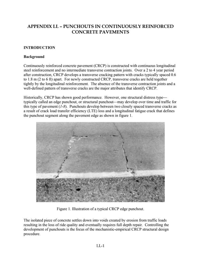
Historically, CRCP has shown good performance. However, one structural distress type—typically called an edge punchout, or structural punchout—may develop over time and traffic for this type of pavement (1-8). Punchouts develop between two closely spaced transverse cracks as a result of crack load transfer efficiency (LTE) loss and a longitudinal fatigue crack that defines the punchout segment along the pavement edge as shown in figure 1.
Figure 1. Illustration of a typical CRCP edge punchout.
The isolated piece of concrete settles down into voids created by erosion from traffic loads resulting in the loss of ride quality and eventually requires full depth repair. Controlling the development of punchouts is the focus of the mechanistic-empirical CRCP structural design procedure.
3
The causes and factors associated with CRCP punchouts have been the topic of many investigations. One of the first studies by LaCoursiere and Darter (1, 2) in 1977 describes the mechanism of edge punchout based on the field investigations of punchout distress in CRCP in Illinois. This study showed the development of high tensile stress at the top of the slab about 1-2 m from the longitudinal edge of the slab as a result of poor load transfer at the surrounding transverse cracks. Crack spacing has also been shown to significantly affect the magnitude of the critical tensile lateral stresses on the top of the slab. These conclusions were reaffirmed by Selezneva (3, 4) in a recent analysis of CRCP distress data for the LTPP sections located in 22 States. About 90 percent of all punchouts observed on LTPP sections were on CRCP segments bound by a pair of transverse cracks spaced at 0.6 m or less.
Zollinger et al. (5) reported that punchouts in field studies were invariably accompanied by severe base erosion and loss of support. As was pointed out by Zollinger and Barenberg (6), poor support conditions can cause rapid deterioration of crack LTE capacity due to excessive shear stresses induced by high deflection. Environmentally induced upward slab curling and warping, coupled with loss of crack load transfer, also contribute to high tensile stresses at the top of the slab.
Deterioration of load transfer effectively isolates the loaded portion of the slab between the deteriorated transverse cracks from the adjacent pavement. As a result, only a narrow concrete panel bounded by two transverse cracks carries the wheel load. This situation leads to the development of high top tensile stresses. As repetitive heavy truck loading continues, a short longitudinal fatigue crack forms between the two transverse cracks. Any further wheel loads cause the portion of the concrete slab bounded by the transverse cracks to develop a short longitudinal fatigue crack, and the pavement edge to break off and settle into the eroded area resulting in an edge punchout.
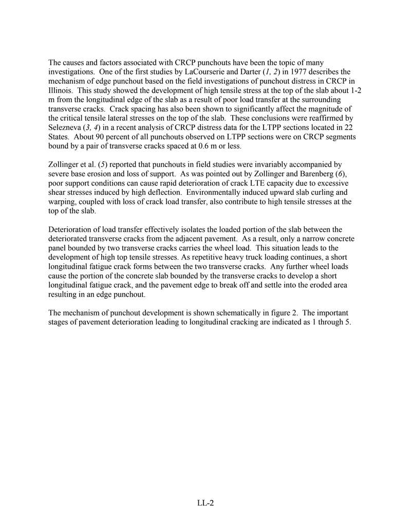
The mechanism of punchout development is shown schematically in figure 2. The important stages of pavement deterioration leading to longitudinal cracking are indicated as 1 through 5.
4
Figure 2. Mechanism of punchout development (4).
In summary, for a punchout to develop, several field conditions typically occur:
- Presence of narrow transverse crack spacing (0.6 m or less) (2 foot or less) in the crack spacing distribution.
- Loss of load transfer efficiency (LTE) across the transverse cracks due to aggregate interlock deterioration from excessive crack opening and heavy repeated loads.
- Loss of support along the pavement edge due to base erosion.
- Negative temperature gradients through the slab thickness and top of slab drying shrinkage further magnify bending stresses.
- Passages of heavy axles causing repetitive cycles of excessive tensile bending stresses leading to longitudinal fatigue cracking that defines the punchout.
The above considerations were utilized in the development of the mechanistic-empirical punchout prediction model presented in this appendix.
Appendix Organization
This appendix consists of the following sections:
- Overview of Existing CRCP Design Models
- Overview of NCHRP 1-37A CRCP Punchout Model
- Step-by-Step Punchout Prediction Procedure
5
- Calibration of NCHRP 1-37A CRCP Punchout Model
- Sensitivity Analysis
- Implementation Considerations
OVERVIEW OF EXISTING CRCP DESIGN MODELS
Existing Models
The design of continuously reinforced concrete pavements (CRCP) has traditionally focused on the design of the steel reinforcement relative to the development of the transverse crack pattern. Punchout development was not directly considered in the 1993 AASHTO design guide. Over the years, a variety of tools have been developed for the analysis of CRCP pavement systems relative to the prediction of transverse crack spacing, crack width, and steel stress. A brief review of different CRCP analysis and design procedures is presented below.
AASHTO CRCP Design Procedure
The AASHTO design procedure is based on the AASHO Road Test pavement serviceability equation. This procedure is based on the analysis of data collected from the doweled jointed concrete pavement sections. No CRCP sections were included in the road test. Current, 1993, AASHTO design procedure for the CRCP pavements consists of two parts (9):
- Longitudinal reinforcement design
- Thickness design
Longitudinal Reinforcement Design
Longitudinal steel is principal reinforcement in the CRCP. Its primary purpose is to control transverse crack spacing that form in the pavement due to concrete volumetric changes. Longitudinal reinforcement is designed to satisfy three limiting criteria: crack spacing, crack width, and allowable steel stress.
Crack spacing recommendations are derived from consideration of spalling and punchouts. To minimize the occurrence of spalling, the maximum spacing between consecutive cracks should be no more than 8 feet. To minimize the potential for the development of punchouts, the minimum desirable crack spacing recommended by AASHTO is 3.5 feet.
Crack width control criterion is based on a consideration of spalling and water penetration. AASHTO recommends that the allowable crack width should not exceed 0.04 inch. To prevent steel fracture and permanent deformation, AASHTO recommends limiting steel stress values to the 75 percentile of the ultimate tensile strength.
Thickness Design
The AASHTO thickness design procedure for CRCP is the same as the thickness design procedure for the jointed pavements. The structural slab thickness design is based upon an
6
预览内容由文件识别整理,表格、公式及文字请以原始文件为准。
原文图片预览
PAGE IMAGES

下载标准文件
2appendices_LL
英语 · PDF · 6 页 · 909.31 KB