标准信息
STANDARD INFORMATION- 标准编号
- 2appendices_JJ
- 所属分类
- 其他国外标准与工程资料
- 文件语言
- 英语
- 文件格式
- 文件页数
- 6 页
- 文件大小
- 779.06 KB
· 更新:
标准简介
OVERVIEW中文简介
标准 2appendices_JJ 的预览内容
English summary
Preview of standard 2appendices_JJ
以上为根据文件整理的内容简介。
标准内容预览
DOCUMENT PREVIEWSHRP P-020 JPCP Transverse Joint Faulting Model
models. The details of each of the faulting models reviewed under this study are described separately in the following sections.
In a SHRP study conducted by Simpson et al. in 1994, titled Early Analysis of LTPP General Pavement Studies Data, separate JPCP faulting models were developed for doweled and non-doweled JPCP.(13) Each of these models are presented as follows:
SHRP P-020 Faulting Model for JPCP With Dowels
FAULTD = CESAL0.25 *[0.0238 + 0.0006 * (JTSPACE/10)2 + 0.0037 * (100/KSTATIC)2 + 0.0039 * (AGE/10)2 − 0.0037 * EDGESUP − 0.0218 * DOWELDIA] (1)
where:
| FAULTD | = Mean transverse doweled joint faulting, in. |
| CESAL | = Cumulative 80-kN (18-kip) ESAL's in traffic lane, millions. |
| JTSPACE | = Mean transverse joint spacing, ft. |
| KSTATIC | = Mean backcalculated static k-value, psi/in. |
| AGE | = Age since construction, years. |
| EDGESUP | = Edge support. 1 = tied PCC shoulder. 0 = any other shoulder type. |
| DOWELDIA | = Diameter of dowels in transverse joints, in. |
Statistics:
| N | = 59. |
| R2 | = 0.534. |
| SEE | = 0.028 in (0.7 mm). |
SHRP P-020 Faulting Model for JPCP Without Dowels
The faulting model developed for non-doweled JPCP was the following:
FAULTND = CESAL0.25 *[−0.07575 + 0.0251 * √AGE + 0.0013 * (PRECIP/10)2 + 0.0012 * (FI * PRECIP/1000) − 0.0378 * DRAIN] (2)
where:
4
Acknowledgment of Sponsorship
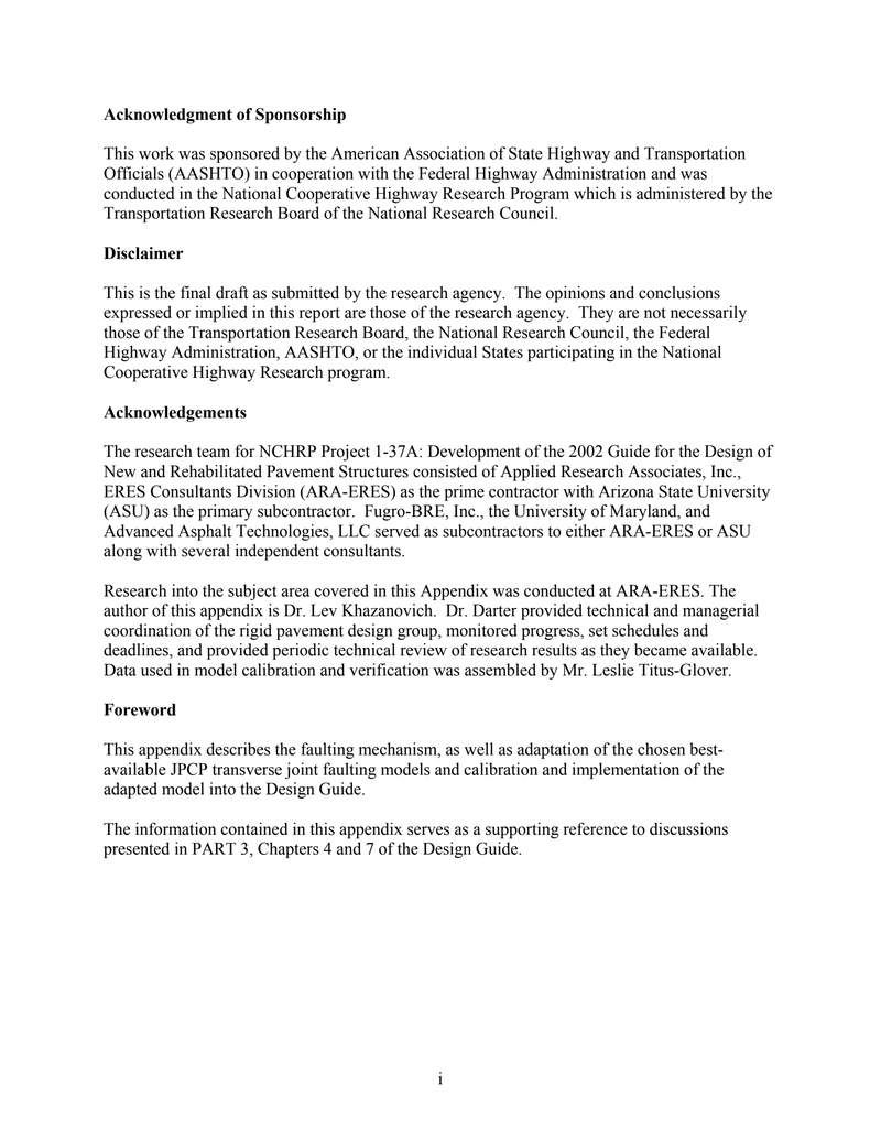
This work was sponsored by the American Association of State Highway and Transportation Officials (AASHTO) in cooperation with the Federal Highway Administration and was conducted in the National Cooperative Highway Research Program which is administered by the Transportation Research Board of the National Research Council.
Disclaimer
This is the final draft as submitted by the research agency. The opinions and conclusions expressed or implied in this report are those of the research agency. They are not necessarily those of the Transportation Research Board, the National Research Council, the Federal Highway Administration, AASHTO, or the individual States participating in the National Cooperative Highway Research program.
Acknowledgements
The research team for NCHRP Project 1-37A: Development of the 2002 Guide for the Design of New and Rehabilitated Pavement Structures consisted of Applied Research Associates, Inc., ERES Consultants Division (ARA-ERES) as the prime contractor with Arizona State University (ASU) as the primary subcontractor. Fugro-BRE, Inc., the University of Maryland, and Advanced Asphalt Technologies, LLC served as subcontractors to either ARA-ERES or ASU along with several independent consultants.
Research into the subject area covered in this Appendix was conducted at ARA-ERES. The author of this appendix is Dr. Lev Khazanovich. Dr. Darter provided technical and managerial coordination of the rigid pavement design group, monitored progress, set schedules and deadlines, and provided periodic technical review of research results as they became available. Data used in model calibration and verification was assembled by Mr. Leslie Titus-Glover.
Foreword
This appendix describes the faulting mechanism, as well as adaptation of the chosen best-available JPCP transverse joint faulting models and calibration and implementation of the adapted model into the Design Guide.
The information contained in this appendix serves as a supporting reference to discussions presented in PART 3, Chapters 4 and 7 of the Design Guide.
2
APPENDIX JJ: TRANSVERSE JOINT FAULTING MODEL
INTRODUCTION
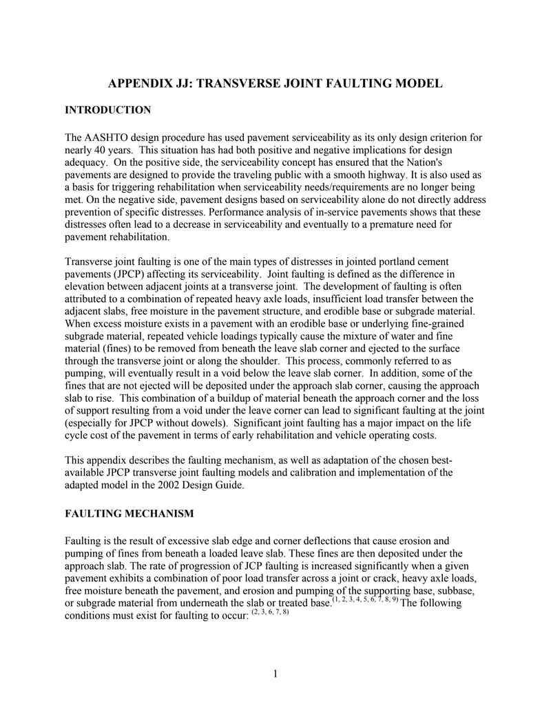
The AASHTO design procedure has used pavement serviceability as its only design criterion for nearly 40 years. This situation has had both positive and negative implications for design adequacy. On the positive side, the serviceability concept has ensured that the Nation's pavements are designed to provide the traveling public with a smooth highway. It is also used as a basis for triggering rehabilitation when serviceability needs/requirements are no longer being met. On the negative side, pavement designs based on serviceability alone do not directly address prevention of specific distresses. Performance analysis of in-service pavements shows that these distresses often lead to a decrease in serviceability and eventually to a premature need for pavement rehabilitation.
Transverse joint faulting is one of the main types of distresses in jointed portland cement pavements (JPCP) affecting its serviceability. Joint faulting is defined as the difference in elevation between adjacent joints at a transverse joint. The development of faulting is often attributed to a combination of repeated heavy axle loads, insufficient load transfer between the adjacent slabs, free moisture in the pavement structure, and erodible base or subgrade material. When excess moisture exists in a pavement with an erodible base or underlying fine-grained subgrade material, repeated vehicle loadings typically cause the mixture of water and fine material (fines) to be removed from beneath the leave slab corner and ejected to the surface through the transverse joint or along the shoulder. This process, commonly referred to as pumping, will eventually result in a void below the leave slab corner. In addition, some of the fines that are not ejected will be deposited under the approach slab corner, causing the approach slab to rise. This combination of a buildup of material beneath the approach corner and the loss of support resulting from a void under the leave corner can lead to significant faulting at the joint (especially for JPCP without dowels). Significant joint faulting has a major impact on the life cycle cost of the pavement in terms of early rehabilitation and vehicle operating costs.
This appendix describes the faulting mechanism, as well as adaptation of the chosen best-available JPCP transverse joint faulting models and calibration and implementation of the adapted model in the 2002 Design Guide.
FAULTING MECHANISM
Faulting is the result of excessive slab edge and corner deflections that cause erosion and pumping of fines from beneath a loaded leave slab. These fines are then deposited under the approach slab. The rate of progression of JCP faulting is increased significantly when a given pavement exhibits a combination of poor load transfer across a joint or crack, heavy axle loads, free moisture beneath the pavement, and erosion and pumping of the supporting base, subbase, or subgrade material from underneath the slab or treated base.(1, 2, 3, 4, 5, 6, 7, 8, 9) The following conditions must exist for faulting to occur:(2, 3, 6, 7, 8)
3
- Significant differential deflections of adjacent slabs that impart energy to the underlying pavement materials. These deflections cause the movement of the saturated underlying pavement material as equilibrium is reestablished, resulting in erosion and pumping. The differential energy across the joint or crack is amplified by several factors, including heavy wheel loads and inadequate load transfer.
- Underlying pavement materials that are erodible. An unstabilized or weakly stabilized material with a high percentage of fines is a prime candidate for erosion.
- The presence of free water in the pavement structure, which leads to the saturation of the underlying materials at the slab/base or treated base/subgrade interface and provides transportation for pumping and erosion of fines.
Because the erosion of material from underneath the leave slab is caused by pumping, it is important to explain pumping in order to understand the mechanism that leads to faulting.
Pumping refers to the ejection of material from beneath the leave slab of a pavement and its deposition along the pavement edge, under the approach slab, or ejection onto the pavement surface through the joints.(4,5,6,7,8) It is caused by the rapid vertical deflection of the leave slab at a joint or crack, which leads to an ejection of fines and water. As a wheel load approaches a joint or crack, the leave slab deflects, causing water and fine material beneath the leave slab to be forced under the approach slab. Some of the water and materials escape through the joint or crack, while the remaining water and fines are distributed under the approach slab. The entire cycle is repeated with the application of axle loads to the pavement. The buildup of loose material under the approach slab, which elevates it at the joint or crack and the depression of the leave slab, results in the difference in elevation across the joint or crack, leading to faulting.
At the AASHO Road Test, although fine material often washed upward through joints and cracks, this was negligible when compared to the amount of material deposited along the edge of the joint or crack.(10) It was also realized that for JCP with a base or subbase experiencing pumping, the material ejected was from the base or subbase (usually including the coarse fraction) rather than the underlying subgrade material. Pumping of the embankment or subgrade soil was generally confined to those sections without a base or subbase or those with very thin base or subbase (< 75 mm) that pumped so severely than all the granular material had been pumped out prior to failure. It is clear, therefore, that the material most susceptible to erosion and pumping is the unstabilized or weakly stabilized (erodible) layer directly beneath the lowest bound layer under the PCC slab.(10)
Results from the AASHO Road Test provided considerable information about the mechanism of pumping. As part of the Road Test, after each rainfall, all pavement sections under traffic were inspected for signs of pumping, and a rough estimate was made of the material pumped. The result was used to calculate a pumping index that approximated the accumulated volume of material ejected per unit length of pavement, averaged over the test section. The following were observed for the Road Test pavements.(10)
- The average pumping index for failed sections (present serviceability = 1.5) was 134.
- The average pumping index for surviving sections was 34.
- There was no clear-cut value of pumping index corresponding to a serviceability of 1.5.
4
- No consistent trend was found relating pumping index to untreated granular subbase thickness.
- There was no significant difference between reinforced and nonreinforced JCP (both had dowels).
- Pumping index decreased as slab thickness increased. However, pumping index increased significantly for pavements with the same slab thickness as more axle loads were applied (or vice versa).
By removing the concrete slab from the failed sections and sampling the underlying material, it was observed that erosion and pumping had apparently been due to the movement of water moving across the top of the subbase. The remaining subbase material was relatively intact. The subbase materials for the failed sections had permeabilities ranging from 0.00288 to 1.512 m/day. Pumping could have been reduced if the subbase material was stabilized and therefore resistant to erosion, or if the infiltrated water could be quickly drained through a subsurface drainage system before the pavement was subjected to heavy wheel loads.(10)
Stabilizing the base material does not always prevent pumping, because pumping can occur directly beneath a treated base overlying a subgrade material susceptible to pumping. This can be reduced by placing a thick granular layer (> 3 in) material between the treated base and subgrade.
Although pumping is the basic mechanism that leads to faulting, several other factors can exacerbate the distress and need to be taken into account. Field results show that the reduced support from upward curling or warping of the slab at the joint or crack will increase pumping pressures because of the higher deflections experienced.(11) The potential for faulting of a pavement is significantly lower in the summer months, when the joints are closed due to thermal expansion.(11) Faulting increases in the other seasons, when the joint width is widest and the underlying materials typically have a higher moisture content.(11, 12) The impact of a heavy wheel load as it crosses the joint or crack is far more pronounced if there is inadequate load transfer. The higher differential deflections that occur due to poor or nonexistent load transfer at the joint or crack lead to more pumping and faulting. However, it is important to note that, even for a pavement with 100 percent load transfer, deflections at the joint or crack can be abnormally high and result in horizontal pumping (movement of material from beneath the leave to beneath the approach slab).(4)
The next few sections describe the results from various research studies that have reported the effect of design features and site condition variables on faulting. Critical response parameters used in the formation of M-E based faulting models and available empirical and M-E models are also presented and discussed.
EXISTING JPCP TRANSVERSE JOINT FAULTING MODELS
In this study, many of the faulting models developed under previous research were reviewed. During the review process, specific attention was paid to the variables chosen for inclusion in the
5
SHRP P-020 JPCP Transverse Joint Faulting Model
models. The details of each of the faulting models reviewed under this study are described separately in the following sections.
In a SHRP study conducted by Simpson et al. in 1994, titled Early Analysis of LTPP General Pavement Studies Data, separate JPCP faulting models were developed for doweled and non-doweled JPCP.(13) Each of these models are presented as follows:
SHRP P-020 Faulting Model for JPCP With Dowels
FAULTD = CESAL0.25 *[0.0238 + 0.0006 * (JTSPACE/10)2 + 0.0037 * (100/KSTATIC)2 + 0.0039 * (AGE/10)2 − 0.0037 * EDGESUP − 0.0218 * DOWELDIA] (1)
where:
| FAULTD | = Mean transverse doweled joint faulting, in. |
| CESAL | = Cumulative 80-kN (18-kip) ESAL's in traffic lane, millions. |
| JTSPACE | = Mean transverse joint spacing, ft. |
| KSTATIC | = Mean backcalculated static k-value, psi/in. |
| AGE | = Age since construction, years. |
| EDGESUP | = Edge support. 1 = tied PCC shoulder. 0 = any other shoulder type. |
| DOWELDIA | = Diameter of dowels in transverse joints, in. |
Statistics:
| N | = 59. |
| R2 | = 0.534. |
| SEE | = 0.028 in (0.7 mm). |
SHRP P-020 Faulting Model for JPCP Without Dowels
The faulting model developed for non-doweled JPCP was the following:
FAULTND = CESAL0.25 *[−0.07575 + 0.0251 * √AGE + 0.0013 * (PRECIP/10)2 + 0.0012 * (FI * PRECIP/1000) − 0.0378 * DRAIN] (2)
where:
4
预览内容由文件识别整理,表格、公式及文字请以原始文件为准。
原文图片预览
PAGE IMAGES

下载标准文件
2appendices_JJ
英语 · PDF · 6 页 · 779.06 KB