标准信息
STANDARD INFORMATION- 标准编号
- EN 10002-1
- 所属分类
- EN 欧洲标准
- 文件语言
- 英语
- 文件格式
- 文件页数
- 6 页
- 文件大小
- 1.02 MB
· 更新:
标准简介
OVERVIEW中文简介
标准 EN 10002-1 的预览内容
English summary
Preview of standard EN 10002-1
以上为根据文件整理的内容简介。
标准内容预览
DOCUMENT PREVIEW4.6.1 percentage permanent extension
increase in the extensometer gauge length, after removal from the test piece of a specified stress, expressed as a percentage of the extensometer gauge length (Le)
4.6.2 percentage yield point extension (Ag)
in discontinuous yielding materials, the extension between the start of yielding and the start of uniform work hardening
NOTE It is expressed as a percentage of the extensometer gauge length (Le)
4.7 percentage reduction of area (Z)
maximum change in cross-sectional area which has occurred during the test (S0 - Su) expressed as a percentage of the original cross-sectional area (S0)
4.8 maximum force (Fm)
the greatest force which the test piece withstands during the test once the yield point has been passed
For materials, without yield point, it is the maximum value during the test.
4.9 stress
force at any moment during the test divided by the original cross-sectional area (S0) of the test piece
4.9.1 tensile strength (Rm)
stress corresponding to the maximum force (Fm)
4.9.2 yield strength
when the metallic material exhibits a yield phenomenon, stress corresponding to the point reached during the test at which plastic deformation occurs without any increase in the force. A distinction is made between :
4.9.2.1 upper yield strength (ReH)
value of stress at the moment when the first decrease in force is observed (see Figure 2)
4.9.2.2 lower yield strength (ReL)
lowest value of stress during plastic yielding, ignoring any initial transient effects (see Figure 2)
4.9.3 proof strength, non-proportional extension (Rp)
stress at which a non-proportional extension is equal to a specified percentage of the extensometer gauge length (Le) (see Figure 3)
NOTE The symbol used is followed by a suffix giving the prescribed percentage, for example : Rp0.2
4.9.4 proof strength, total extension (Rt)
stress at which total extension (elastic extension plus plastic extension) is equal to a specified percentage of the extensometer gauge length (Le) (see Figure 4)
NOTE The symbol used is followed by a suffix giving the prescribed percentage, for example : Rt0.5
6
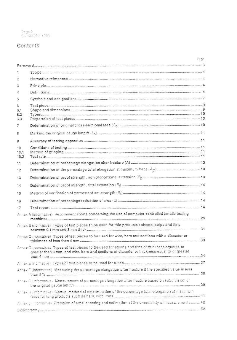
Contents
| Page | |
|---|---|
| Foreword | 3 |
| 1 Scope | 4 |
| 2 Normative references | 4 |
| 3 Principle | 4 |
| 4 Definitions | 4 |
| 5 Symbols and designations | 7 |
| 6 Test piece | 9 |
| 6.1 Shape and dimensions | 9 |
| 6.2 Types | 10 |
| 6.3 Preparation of test pieces | 10 |
| 7 Determination of original cross-sectional area (S0) | 10 |
| 8 Marking the original gauge length (L0) | 11 |
| 9 Accuracy of testing apparatus | 11 |
| 10 Conditions of testing | 11 |
| 10.1 Method of gripping | 11 |
| 10.2 Test rate | 11 |
| 11 Determination of percentage elongation after fracture (A) | 12 |
| 12 Determination of the percentage total elongation at maximum force (Agt) | 13 |
| 13 Determination of proof strength, non proportional extension (Rp) | 13 |
| 14 Determination of proof strength, total extension (Rt) | 14 |
| 15 Method of verification of permanent set strength (Rz) | 14 |
| 16 Determination of percentage reduction of area (Z) | 14 |
| 17 Test report | 14 |
| Annex A (informative) Recommendations concerning the use of computer controlled tensile testing machines | 26 |
| Annex B (informative) Types of test pieces to be used for thin products: sheets, strips and flats between 0,1 mm and 3 mm thick | 31 |
| Annex C (normative) Types of test pieces to be used for wire, bars and sections with a diameter or thickness of less than 4 mm | 33 |
| Annex D (normative) Types of test pieces to be used for sheets and flats of thickness equal to or greater than 3 mm, and wire, bars and sections of diameter or thickness equal to or greater than 4 mm | 34 |
| Annex E (normative) Types of test pieces to be used for tubes | 37 |
| Annex F (informative) Measuring the percentage elongation after fracture if the specified value is less than 5 % | 38 |
| Annex G (informative) Measurement of percentage elongation after fracture based on subdivision of the original gauge length | 39 |
| Annex H (informative) Manual method of determination of the percentage total elongation at maximum force for long products such as bars, wire, rods | 41 |
| Annex J (informative) Precision of tensile testing and estimation of the uncertainty of measurement | 42 |
| Bibliography | 52 |
2
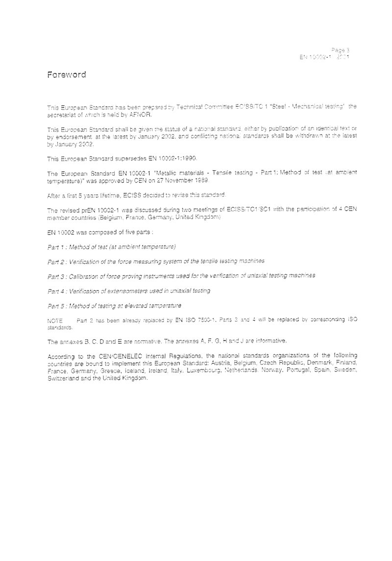
Foreword
This European Standard has been prepared by Technical Committee ECISS/TC 1 "Steel - Mechanical testing", the secretariat of which is held by AFNOR.
This European Standard shall be given the status of a national standard, either by publication of an identical text or by endorsement, at the latest by January 2002, and conflicting national standards shall be withdrawn at the latest by January 2002.
This European Standard supersedes EN 10002-1:1990.
The European Standard EN 10002-1 "Metallic materials - Tensile testing - Part 1: Method of test (at ambient temperature)" was approved by CEN on 27 November 1999.
After a first 5 years lifetime, ECISS decided to revise this standard.
The revised prEN 10002-1 was discussed during two meetings of ECISS/TC1/SC1 with the participation of 4 CEN member countries (Belgium, France, Germany, United Kingdom).
EN 10002 was composed of five parts:
Part 1: Method of test (at ambient temperature)
Part 2: Verification of the force measuring system of the tensile testing machines
Part 3: Calibration of force proving instruments used for the verification of uniaxial testing machines
Part 4: Verification of extensometers used in uniaxial testing
Part 5: Method of testing at elevated temperature
NOTE Part 2 has been already replaced by EN ISO 7500-1. Parts 3 and 4 will be replaced by corresponding ISO standards.
The annexes B, C, D and E are normative. The annexes A, F, G, H and J are informative.
According to the CEN/CENELEC Internal Regulations, the national standards organizations of the following countries are bound to implement this European Standard: Austria, Belgium, Czech Republic, Denmark, Finland, France, Germany, Greece, Iceland, Ireland, Italy, Luxembourg, Netherlands, Norway, Portugal, Spain, Sweden, Switzerland and the United Kingdom.
3
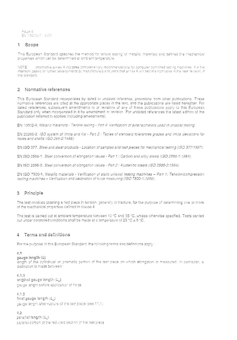
1 Scope
This European Standard specifies the method for tensile testing of metallic materials and defines the mechanical properties which can be determined at ambient temperature.
NOTE Informative annex A indicates complementary recommendations for computer-controlled testing machines. It is the intention, based on further developments by manufacturers and users that annex A will become normative in the next revision of this standard.
2 Normative references
This European Standard incorporates by dated or undated reference, provisions from other publications. These normative references are cited at the appropriate places in the text, and the publications are listed hereafter. For dated references, subsequent amendments to or revisions of any of these publications apply to this European Standard only when incorporated in it by amendment or revision. For undated references the latest edition of the publication referred to applies (including amendments).
EN 10002-4, Metallic materials - Tensile testing - Part 4: Verification of extensometers used in uniaxial testing.
EN ISO 286-2, ISO system of limits and fits - Part 2: Tables of standard tolerance grades and limit deviations for holes and shafts (ISO 286-2:1988).
EN ISO 377, Steel and steel products - Location of samples and test pieces for mechanical testing (ISO 377:1997).
EN ISO 2566-1, Steel conversion of elongation values - Part 1: Carbon and alloy steels (ISO 2566-1:1984).
EN ISO 2566-2, Steel conversion of elongation values - Part 2: Austenitic steels (ISO 2566-2:1984).
EN ISO 7500-1, Metallic materials - Verification of static uniaxial testing machines - Part 1: Tension/compression testing machines - Verification and calibration of force measuring (ISO 7500-1:1999).
3 Principle
The test involves straining a test piece in tension, generally to fracture, for the purpose of determining one or more of the mechanical properties defined in clause 4.
The test is carried out at ambient temperature between 10 °C and 35 °C, unless otherwise specified. Tests carried out under controlled conditions shall be made at a temperature of 23 °C ± 5 °C.
4 Terms and definitions
For the purpose of this European Standard the following terms and definitions apply:
4.1 gauge length (L)
length of the cylindrical or prismatic portion of the test piece on which elongation is measured. In particular, a distinction is made between:
4.1.1 original gauge length (L0)
gauge length before application of force
4.1.2 final gauge length (Lu)
gauge length after rupture of the test piece (see 11.1)
4.2 parallel length (Lc)
parallel portion of the reduced section of the test piece
4
4.3 elongation
increase in the original gauge length (L0) at any moment during the test
4.4 percentage elongation
elongation expressed as a percentage of the original gauge length (L0)
4.4.1 percentage permanent elongation
increase in the original gauge length of a test piece after removal of a specified stress (see 4.9), expressed as a percentage of the original gauge length (L0)
4.4.2 percentage elongation after fracture (A)
permanent elongation of the gauge length after fracture (Lu - L0), expressed as a percentage of the original gauge length (L0)
NOTE in the case of proportional test pieces, only if the original gauge length is other than 5.65 √S0 1) where S0 is the original cross-sectional area of the parallel length, the symbol A should be supplemented by an index indicating the coefficient of proportionality used, for example:
A11,3 = percentage elongation of a gauge length (L0) of 11,3 √S0
In the case of non-proportional test pieces, the symbol A should be supplemented by an index indicating the original gauge length used, expressed in millimetres, for example:
A80 mm = percentage elongation of a gauge length (L0) of 80 mm.
4.4.3 percentage total elongation at fracture (At)
total elongation (elastic elongation plus plastic elongation) of the gauge length at the moment of fracture expressed as a percentage of the original gauge length (L0)
4.4.4 percentage elongation at maximum force
increase in the gauge length of the test piece at maximum force, expressed as a percentage of the original gauge length (L0)
NOTE A distinction is made between the percentage total elongation at maximum force (Agt) and the percentage non-proportional elongation at maximum force (Ag) (see Figure 1).
4.5 extensometer gauge length (Le)
length of the parallel portion of the test piece used for the measurement of extension by means of an extensometer
NOTE It is recommended that for measurement of yield and proof strength parameters Le ≥ L0/2. It is further recommended that for measurement of parameters "at" or "after" maximum force, Le is approximately equal to L0.
4.6 extension
increase in the extensometer gauge length (Le) at a given moment of the test
1) 5,65 √S0 = 5 √(4S0/π)
5
4.6.1 percentage permanent extension
increase in the extensometer gauge length, after removal from the test piece of a specified stress, expressed as a percentage of the extensometer gauge length (Le)
4.6.2 percentage yield point extension (Ag)
in discontinuous yielding materials, the extension between the start of yielding and the start of uniform work hardening
NOTE It is expressed as a percentage of the extensometer gauge length (Le)
4.7 percentage reduction of area (Z)
maximum change in cross-sectional area which has occurred during the test (S0 - Su) expressed as a percentage of the original cross-sectional area (S0)
4.8 maximum force (Fm)
the greatest force which the test piece withstands during the test once the yield point has been passed
For materials, without yield point, it is the maximum value during the test.
4.9 stress
force at any moment during the test divided by the original cross-sectional area (S0) of the test piece
4.9.1 tensile strength (Rm)
stress corresponding to the maximum force (Fm)
4.9.2 yield strength
when the metallic material exhibits a yield phenomenon, stress corresponding to the point reached during the test at which plastic deformation occurs without any increase in the force. A distinction is made between :
4.9.2.1 upper yield strength (ReH)
value of stress at the moment when the first decrease in force is observed (see Figure 2)
4.9.2.2 lower yield strength (ReL)
lowest value of stress during plastic yielding, ignoring any initial transient effects (see Figure 2)
4.9.3 proof strength, non-proportional extension (Rp)
stress at which a non-proportional extension is equal to a specified percentage of the extensometer gauge length (Le) (see Figure 3)
NOTE The symbol used is followed by a suffix giving the prescribed percentage, for example : Rp0.2
4.9.4 proof strength, total extension (Rt)
stress at which total extension (elastic extension plus plastic extension) is equal to a specified percentage of the extensometer gauge length (Le) (see Figure 4)
NOTE The symbol used is followed by a suffix giving the prescribed percentage, for example : Rt0.5
6
预览内容由文件识别整理,表格、公式及文字请以原始文件为准。
原文图片预览
PAGE IMAGES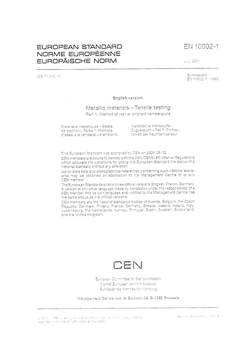
下载标准文件
EN 10002-1
英语 · PDF · 6 页 · 1.02 MB