NF P94-093-中文版
土壤:勘测和实验 - 材料压实特性测定 - 常规 Proctor 实验 - 变更 Proctor 实验
NF P94-093-中文版
Soil - Investigation and testing - Determination of compaction characteristics of materials - Standard Proctor test - Modified Proctor test
标准信息
STANDARD INFORMATION- 标准编号
- NF P94-093-中文版
- 所属分类
- NF 法国标准
- 发布机构
- AFNOR
- 版本年份
- 1999
- 文件语言
- 英语
- 文件格式
- 文件页数
- 6 页
- 文件大小
- 1.02 MB
中文名称为参考译名,文件语言以原文为准。
· 更新:
标准简介
OVERVIEW中文简介
本标准规定了通过常规 Proctor 实验和变更 Proctor 实验测定路基材料压实特性(最佳含水量和最大干密度)的方法。适用于 NF P11-300 分类中最大粒径不超过 20mm 的天然或处理过的土壤材料,用于确定填料和路基层施工中的压实规范参数。
English summary
This standard specifies methods for determining the compaction characteristics (optimum moisture content and maximum dry density) of road subgrade materials using Standard and Modified Proctor tests. It applies to soils classified under NF P11-300 with a maximum particle size not exceeding 20mm, used for defining compaction specifications in fill and sub-base construction.
以上为根据文件整理的内容简介。
相关标签
标准内容预览
DOCUMENT PREVIEW5. 设备
对其进行压实作业。根据观察到的每一个含水量数值,可以确定材料的干密度,并可以绘制出一条随着含水量数值变化而变化的干密度曲线。
一般说来,这个被称之为 proctor 曲线的曲线就是根据含水量的特定数值而获得的材料的干密度最大值。根据所进行的实验,这两个数值被称为常规 Proctor 压实特性或变更 Proctor 压实特性。
注释 1:本标准特别考虑用 5 个点来确定 proctor 曲线。这 5 个点是最少数量,用更多点来确定这一曲线的实验也符合标准。
注释 2:因为这些实验都在模具内的实验样件上进行,并且也是根据本标准所规定的操作方法进行的压实,故通常在进行确定即时 CBR 指数与/或浸水后与/或当时显示指数的实验时,也同时进行 proctor 实验(参阅 NF P 94-078 标准)。
5.1 专用设备
专用设备包括:
— 一块压实底座,由水平面平整的混凝土块构成,水平面至少要 30cm×30cm,厚度至少 30cm。
— 两个模具模型:
— Proctor 模具;
— CBR 模具。
这两个模型由模具主体、底座和垫块构成。模具的主体可以为单体或分体式。这些部分的形状和功能性尺寸应遵守附图 1 的规定。
CBR 模具还包括一个间隔圆盘,其形状和尺寸需符合遵守附图 1 的规定。
— 两个手工打夯机模型:
— 所谓的“常规 Proctor 打夯机”,是由一个直径为 51mm±0.1mm 的圆柱形打桩机构成。为了防止其从 305mm±1mm 的高度掉落,该打桩机将包裹在一个外罩内。该可移动机组的质量在 2490g±2g。该打夯机的形状和功能尺寸应该满足附图 1 中的指数。
— 所谓的“变更 Proctor 打夯机”和“常规 Proctor 打夯机”设计类似,但可移动机组的质量在 4535g±2g,允许掉落高度在 305mm±1mm。该打夯机的形状和其他功能尺寸应该符合图 1 上的指数。
— 一个砌平尺,由钢刀构成,形状和尺寸应该符合附图 1 中的指数。
— 一个机械压实装置,如果满足以下条件,可方便使用:
1)质量、直径、打桩机允许电骤高度、外罩厚度如附表 1 所规定;
2)压实分配的模式遵守第 7.2 段的要求;
6
Révision de la présente publication
Le contenu technique des publications de la CEI est constamment revu par la Commission afin d'assurer qu'il reflète bien l'état actuel de la technique.
Les renseignements relatifs à ce travail de révision, à l'établissement des éditions révisées et aux mises à jour peuvent être obtenus auprès des Comités nationaux de la CEI et en consultant les documents ci-dessous :
- Bulletin de la CEI
- Annuaire de la CEI
- Catalogue des publications de la CEI
Publié annuellement
Terminologie
En ce qui concerne la terminologie générale, le lecteur se reportera à la Publication 50 de la CEI : Vocabulaire Electrotechnique International (VEI), qui est établie sous forme de chapitres séparés traitant chacun d'un sujet défini, l'Index général étant publié séparément. Des détails complets sur le VEI peuvent être obtenus sur demande.
Les termes et définitions figurant dans la présente publication ont été soit repris du VEI, soit spécifiquement approuvés aux fins de cette publication.
Symboles graphiques et littéraux
Pour les symboles graphiques, symboles littéraux et signes d'usage général approuvés par la CEI, le lecteur consultera :
- la Publication 27 de la CEI : Symboles littéraux à utiliser en électrotechnique ;
- la Publication 617 de la CEI : Symboles graphiques pour schémas.
Les symboles et signes contenus dans la présente publication ont été soit repris des Publications 27 ou 617 de la CEI, soit spécifiquement approuvés aux fins de cette publication.
Publications de la CEI établies par le même Comité d'Etudes
L'attention du lecteur est attirée sur la page 3 de la couverture, qui énumère les publications de la CEI préparées par le Comité d'Etudes qui a établi la présente publication.
Revision of this publication
The technical content of IEC publications is kept under constant review by the IEC, thus ensuring that the content reflects current technology.
Information on the work of revision, the issue of revised editions and amendment sheets may be obtained from IEC National Committees and from the following IEC sources :
- IEC Bulletin
- IEC Yearbook
- Catalogue of IEC Publications
Published yearly
Terminology
For general terminology, readers are referred to IEC Publication 50 : International Electrotechnical Vocabulary (IEV), which is issued in the form of separate chapters each dealing with a specific field, the General Index being published as a separate booklet. Full details of the IEV will be supplied on request.
The terms and definitions contained in the present publication have either been taken from the IEV or have been specifically approved for the purpose of this publication.
Graphical and letter symbols
For graphical symbols, and letter symbols and signs approved by the IEC for general use, readers are referred to :
- IEC Publication 27 : Letter symbols to be used in electrical technology ;
- IEC Publication 617 : Graphical symbols for diagrams.
The symbols and signs contained in the present publication have either been taken from IEC Publications 27 or 617, or have been specifically approved for the purpose of this publication.
IEC publications prepared by the same Technical Committee
The attention of readers is drawn to the inside of the back cover, which lists IEC publications issued by the Technical Committee which has prepared the present publication.
2
SOMMAIRE
| pages | |
|---|---|
| Extrait de l'arrêté du 12 février 2004 relatif à la composition du cahier des clauses techniques générales applicables aux marchés publics de travaux et approuvant ou modifiant divers fascicules | III |
| Circulaire n° 2004-16 du 4 mars 2004 relative à la modification du fascicule 56 du Cahier des clauses techniques générales applicables aux marchés publics de travaux | V |
| Rapport de présentation | IX |
| Fascicule 56 | |
| Table des matières | 1 |
| Fascicule 56 | 7 |
| Annexes | 77 |
| Liste des membres du groupe de travail | 129 |
TABLE DES MATIÈRES
| Pages | |
| Extraits du décret n° 83-253 du 8 avril 1987 relatif à la composition du cahier des clauses techniques générales applicables aux marchés publics de travaux et approuvant ou modifiant divers fascicules | V |
| Fascicule n° 76 — Textes et commentaires | 2 |
| Annexes | 41 |
| Rapport de présentation | 71 |
5.2 专用设备

图 1—摩擦摆
① 摆(垫板轴长 50 厘米)
② 橡胶垫板
③ 指针
④ 标明刻度的刻度盘
⑤ 水平仪
⑥ 齿条
⑦ 摆锤水平悬挂点和起动开关
—摩擦摆(如图 1):由一个固定摆锤的机构构成,摆锤端部带有橡胶垫板。整个这一部分重量约为 10 千克,其中主要构件有:
-- 机架:包括一个配备了⑤ 水平仪和三个可调节高度的支脚的底座;一根带⑥ 齿条的柱子。
-- 设备顶部,能沿柱子滑动,并可以通过齿条上的按钮调节高度,然后用螺栓将其位置固定。顶部还含有一个带刻度的刻度盘、指针的摩擦环和一个能通过⑦起动开关将摆锤固定在一定水平位置的装置。
ISO 657-1 : 1988 (E)
Table 1 — Dimensions and sectional properties of hot-rolled equal-leg angles (concluded)
| Designation | Mass kg/m | Sectional area cm² | Dimensions | Distances of centre of gravity | Sectional properties about axes | |||||||||||
|---|---|---|---|---|---|---|---|---|---|---|---|---|---|---|---|---|
| X-X = Y-Y | U-U | V-V | ||||||||||||||
| A mm | l mm | rroot mm | cx = cy cm | cu cm | cv cm | Ix = Iy cm⁴ | rx = ry cm | Zx = Zy cm³ | Iu cm⁴ | ru cm | Iv cm⁴ | rv cm | Zv cm³ | |||
| (1) | (2) | (3) | (4) | (5) | (6) | (7) | (8) | (9) | (10) | (11) | (12) | (13) | (14) | (15) | (16) | (17) |
| 200 × 200 × 16 | 48,5 | 61,8 | 200 | 16 | 18 | 5,52 | 14,1 | 7,81 | 2 340 | 6,16 | 162 | 3 720 | 7,76 | 960 | 3,94 | 123 |
| 200 × 200 × 20 | 59,9 | 76,3 | 200 | 20 | 18 | 5,68 | 14,1 | 8,04 | 2 850 | 6,11 | 199 | 4 530 | 7,70 | 1 170 | 3,92 | 146 |
| 200 × 200 × 24 | 71,1 | 90,6 | 200 | 24 | 18 | 5,84 | 14,1 | 8,26 | 3 330 | 6,06 | 235 | 5 280 | 7,64 | 1 380 | 3,90 | 167 |
| 250 × 250 × 28 | 104 | 133 | 250 | 28 | 18 | 7,24 | 17,7 | 10,2 | 7 700 | 7,62 | 433 | 12 200 | 9,61 | 3 170 | 4,89 | 309 |
| 250 × 250 × 35 | 128 | 163 | 250 | 35 | 18 | 7,50 | 17,7 | 10,6 | 9 260 | 7,54 | 529 | 14 700 | 9,48 | 3 860 | 4,87 | 364 |
NOTES
- Member countries may choose, to be included in their national standards, the sizes which are required to meet their demand.
- For the angles so chosen, only thicknesses which can be rolled in their mills to meet the demand of the users may be selected from the list of thicknesses corresponding to equal angles in table 1.
- The sectional area has been calculated using the formula
S = [l/2 A - l) + 0,214 6 (rroot² - 2rtoe²)] × 1/100
where
S is the sectional area, in square centimetres;
l is the thickness, in millimetres;
rroot is the root radius, in millimetres;
rtoe is the toe radius, in millimetres;
A is the leg length, in millimetres.
- Mass is calculated on the basis of density of steel of 7,85 kg/dm³.
4
预览内容由文件识别整理,表格、公式及文字请以原始文件为准。
原文图片预览
PAGE IMAGES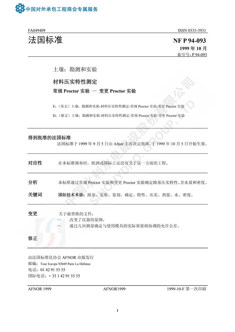
下载标准文件
NF P94-093-中文版
英语 · PDF · 6 页 · 1.02 MB