IEC 60071-4 Insulation Coordination-4 Computationa
绝缘配合 – 第4部分:绝缘配合和电力网络建模的计算指南
IEC 60071-4 Insulation Coordination-4 Computational guide to insulation coordination and modelling of electrical networks
Insulation co-ordination – Part 4: Computational guide to insulation co-ordination and modelling of electrical networks
标准信息
STANDARD INFORMATION- 标准编号
- IEC 60071-4 Insulation Coordination-4 Computationa
- 所属分类
- IEC 国际电工标准
- 发布机构
- IEC
- 版本年份
- 2004
- 文件语言
- 英语
- 文件格式
- 文件页数
- 6 页
- 文件大小
- 1.37 MB
中文名称为参考译名,文件语言以原文为准。
· 更新:
标准简介
OVERVIEW中文简介
该标准提供了绝缘配合和电力网络建模的计算指南。它涵盖了不同类型过电压(如暂时过电压、慢波前过电压、快波前过电压等)的研究方法,并给出了架空线、地下电缆及开关设备电弧建模的具体指导。
English summary
This standard provides a computational guide for insulation co-ordination and the modelling of electrical networks. It covers methods for studying different types of overvoltages (such as TOV, SFO, FFO) and offers specific guidance on modelling overhead lines, underground cables, and circuit-breaker arcs.
以上为根据文件整理的内容简介。
相关标签
标准内容预览
DOCUMENT PREVIEWList of Figures
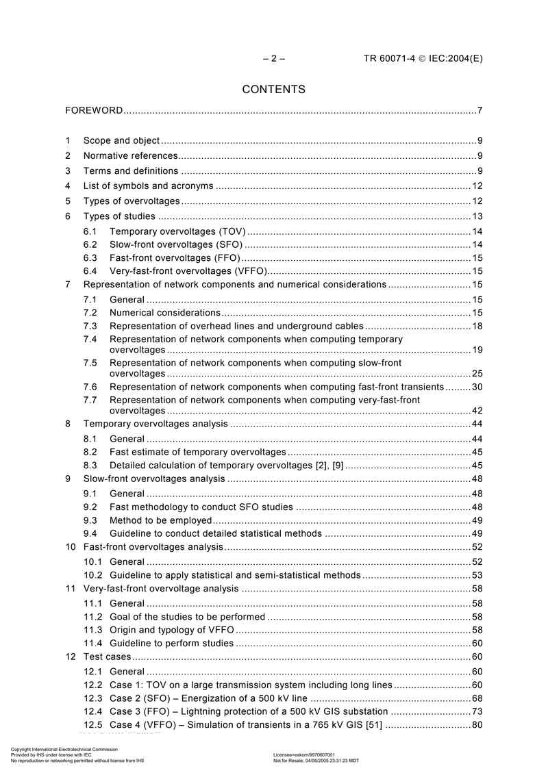
Figure 28 – TOV at CHM7 – Electromagnetic transient simulation with 588 kV and 612 kV permanent surge arresters. 67
Figure 29 – TOV at LVD7 – Electromagnetic transient simulation with 484 kV switched metal-oxide surge arresters. 67
Figure 30 – TOV at CHM7 – Electromagnetic transient simulation with 484 kV switched metal-oxide surge arresters. 67
Figure 31 – Representation of the system. 68
Figure 32 – Auxiliary contact and main. 70
Figure 33 – An example of cumulative probability function of phase-to-earth overvoltages and of discharge probability of insulation in a configuration with trapped charges and insertion resistors. 72
Figure 34 – Number of failure for 1 000 operations versus the withstand voltage of the insulation. 72
Figure 35 – Schematic diagram of a 500 kV GIS substation intended for lightning studies. 74
Figure 36 – Waveshape of the lightning stroke current. 75
Figure 37 – Response surface approximation (failure and safe-state representation for one GIS section (node)). 77
Figure 38 – Limit-state representation in the probability space of the physical variables. 79
Figure 39 – Single-line diagram of a 765 kV GIS with a closing disconnector. 81
Figure 40 – Simulation scheme of the 765 kV GIS part involved in the transient phenomena of interest. 81
Figure 41 – 4 ns ramp. 84
Figure 42 – Switch operation. 85
Figure A.1 – Pi-model. 86
Figure A.2 – Representation of the single conductor line. 87
Figure B.1 – SF6 circuit-breaker switching. 91
Figure C.1 – Example of a failure domain. 96
Figure D.1 – The line and the reactance are energized at the same time. 99
Figure D.2 – Energization configuration of the line minimizing the risk of temporary overvoltage. 100
Figure D.3 – Malfunction of a circuit-breaker pole during energization of a transformer. 102
Figure D.4 – Voltage in substation B phase A whose pole has not closed. 103
Figure D.5 – Voltage in substation B phase B whose pole closed correctly. 103
Figure D.6 – Voltage in substation B phase A where the breaker failed to close (configuration of Figure D.2). 104
Figure E.1 – Electric circuit used to perform closing overvoltage calculations. 105
Figure E.2 – Calculated overvoltage distribution – Two estimated Gauss probability functions resulting from two different fitting criteria (the U2% and U10% guarantees a good fitting of the most dangerous overvoltages). 107
Figure E.3 – Example of switching overvoltage between phases A and B and phase-to-earth (A and B). 109
Figure E.4 – Voltage distribution along the GIL (ER-energization ED-energization under single-phase fault ChPg-trapped charges). 110
Figure F.1 – Test circuit (Copyright1998 IEEE [48]). 113
Figure F.2 – Terminal voltage and current of GCB model (Copyright 1998 IEEE [48]). 113
Figure F.3 – Measured arc parameter (Copyright 1998 IEEE [48]). 114
6
2 Scope
2
NORME INTERNATIONALE INTERNATIONAL STANDARD МЕЖДУНАРОДНЫЙ СТАНДАРТ
|
NORME INTERNATIONALE INTERNATIONAL STANDARD МЕЖДУНАРОДНЫЙ СТАНДАРТ |
CEI IEC 50(426) Première édition First edition 1990-10 Vocabulaire Electrotechnique InternationalChapitre 426 : Matériel électrique pour atmosphères explosives International Electrotechnical VocabularyChapter 426 : Electrical apparatus for explosive atmospheres Международный Электротехнический СловарьГлава 426 : Электрооборудование для взрывоопасных сред © CEI 1990 Droits de reproduction réservés - Copyright - all rights reserved - Право издания охраняется законом Aucune partie de cette publication ne peut être reproduite ni utilisée sous quelque forme que ce soit et par aucun procédé, électronique ou mécanique, y compris la photocopie et les microfilms, sans l'accord écrit de l'éditeur. No part of this publication may be reproduced or utilized in any form or by any means, electronic or mechanical, including photocopying and microfilm, without permission in writing from the publisher. Запрещается Без письменного разрешения издателя воспроизведение или копирование этой публикации или ее части в любой форме или любыми средствами — электронными или механическими, включая фотоконю и микрофильм. Bureau central de la Commission Electrotechnique Internationale 3, rue de Varembé Genève Suisse
|
50(715) © IEC:1996
CONTENTS
| FOREWORD | VII | |
| PREFACE | VII | |
| Sections | ||
| 715-01 | Basic terms | 1 |
| 715-02 | Resources | 10 |
| 715-03 | Calls | 17 |
| 715-04 | Times and delays | 22 |
| 715-05 | Traffic | 24 |
| 715-06 | Circuit groups | 32 |
| 715-07 | Traffic engineering | 34 |
| 715-08 | Networks | 41 |
| 715-09 | Circuit switched networks | 46 |
| 715-10 | Message switched networks | 51 |
| 715-11 | Packet switched networks | 52 |
| Index | 53 |
:current
Foreword
This document (EN 10216-3:2002) has been prepared by Technical Committee EC/TC 29, "Steel tubes and fittings for steel tubes", the secretariat of which is held by UNI.
This European Standard shall be given the status of a national standard, either by publication of an identical text or by endorsement, at the latest by November 2002, and conflicting national standards shall be withdrawn at the latest by November 2002.
This document has been prepared under a mandate given to CEN by the European Commission and the European Free Trade Association, and supports essential requirements of EU Directive(s).
For relationship with EU Directive(s), see informative annex ZA, which is an integral part of this document.
Other Parts of EN 10216 are:
| Part 1: | Non-alloy steel tubes with specified room temperature properties |
| Part 2: | Non-alloy and alloy steel tubes with specified elevated temperature properties |
| Part 4: | Non-alloy and alloy steel tubes with specified low temperature properties |
| Part 5: | Stainless steel tubes |
Another European Standard series covering tubes for pressure purposes is:
| EN 10217: | Welded steel tubes for pressure purposes |
According to the CEN/CENELEC Internal Regulations, the national standards organizations of the following countries are bound to implement this European Standard: Austria, Belgium, Czech Republic, Denmark, Finland, France, Germany, Greece, Iceland, Ireland, Italy, Luxembourg, Malta, Netherlands, Norway, Portugal, Spain, Sweden, Switzerland and the United Kingdom.
5
1 Scope
This Part of EN 10216 specifies the technical delivery conditions in two test categories for seamless tubes of circular cross section, made of weldable alloyed fine grained steel.
2 Normative references
This European Standard incorporates by date or undated reference, provisions from other publications. These normative references are cited at the appropriate places in the text and the publications are listed hereafter. For date references, subsequent amendments to or revisions of, any of these publications apply to this European Standard only when incorporated in it by amendment or revision. For undated references the latest edition of the publication referred to applies (including amendments).
The requirements of this European Standard rule when they differ from those in the standards and documents referred to below:
EN 10002-1, Metallic materials - Tensile testing - Part 1: Method of test (at ambient temperature).
EN 10002-5, Metallic materials - Tensile testing - Part 5: Method of testing (at elevated temperature).
EN 10020, Definitions and classification of grades of steel.
EN 10021, General technical delivery requirements for steel and iron products.
EN 10045-1, Metallic materials - Charpy impact test - Part 1: Test method.
EN 10052, Vocabulary of heat treatment terms for ferrous products.
EN 10204, Metallic products - Types of inspection documents.
EN 10027-1, Designation systems for steels - Part 1: Steel names, principle symbols.
EN 10027-2, Designation systems for steels Part 2: Numerical systems.
ENV 10220, Seamless and welded steel tubes - Dimensions and masses per unit length
EN 10233, Metallic materials - Tubes - Flattening test.
EN 10234, Metallic materials - Tubes - Drift expanding test.
EN 10236, Metallic materials - Tubes - Ring expanding test.
EN 10237, Metallic materials - Tubes - Ring tensile test.
EN 10246-1, Non-Destructive Testing of steel tubes Part 1: Automatic electromagnetic testing of seamless and welded (except submerged arc welded) ferromagnetic steel tubes for verification of hydraulic leak-tightness.
EN 10246-5, Non-Destructive Testing of steel tubes - Part 5: Automatic full peripheral magnetic transducer/flux leakage testing of seamless and welded (except submerged arc-welded) ferromagnetic steel tubes for the detection of longitudinal imperfections.
EN 10246-6, Non-Destructive Testing of steel tubes - Part 6: Automatic full peripheral ultrasonic testing of seamless steel tubes for the detection of transverse imperfections.
EN 10246-7, Non-Destructive Testing of steel tubes - Part 7: Automatic full peripheral ultrasonic testing of seamless and welded (except submerged arc welded) steel tubes for the detection of longitudinal imperfections.
6
预览内容由文件识别整理,表格、公式及文字请以原始文件为准。
原文图片预览
PAGE IMAGES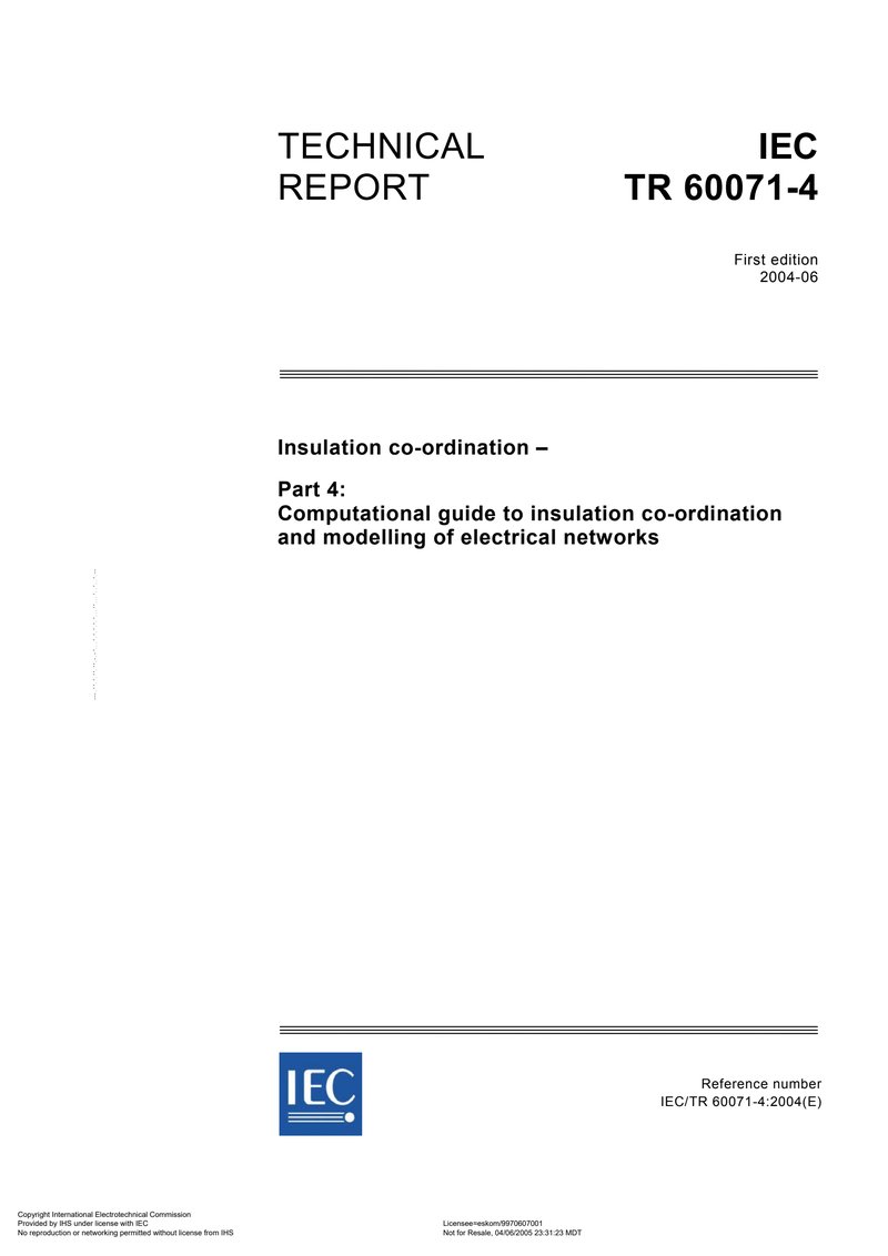
下载标准文件
IEC 60071-4 Insulation Coordination-4 Computationa
英语 · PDF · 6 页 · 1.37 MB