DIN EN 10045
金属材料 - 夏比冲击试验 第1部分:试验方法
DIN EN 10045
Metallic materials — Charpy impact test Part 1: Test method
标准信息
STANDARD INFORMATION- 标准编号
- DIN EN 10045
- 所属分类
- DIN 德国标准
- 发布机构
- CEN
- 版本年份
- 1990
- 文件语言
- 英语
- 文件格式
- 文件页数
- 6 页
- 文件大小
- 178.11 KB
中文名称为参考译名,文件语言以原文为准。
· 更新:
标准简介
OVERVIEW中文简介
该标准规定了金属材料的夏比冲击试验方法,包括U型缺口和V型缺口试样的制备、尺寸公差及试验条件。它适用于评估金属材料在冲击载荷下的韧性性能,是机械物理测试领域的基础标准。
English summary
This standard specifies the test method for the Charpy impact test on metallic materials, covering the preparation, dimensions, and tolerances of U-notch and V-notch test pieces. It is applicable for assessing the toughness of metallic materials under impact loading and serves as a fundamental standard in mechanical and physical testing.
以上为根据文件整理的内容简介。
相关标签
标准内容预览
DOCUMENT PREVIEWCharpy impact test on metallic materials
Test method
| Metallische Werkstoffe; Kerbschlagbiegeversuch nach Charpy; Prüfverfahren | This standard, together with DIN 50 115, April 1991 edition, supersedes DIN 50 115, February 1975 edition. |
European Standard EN 10 045-1 : 1991 has the status of a DIN Standard.
A comma is used as the decimal marker.
National foreword
This standard has been prepared by ECISS/TC 1a.
The responsible German body involved in the preparation of this standard was the Normenausschuß Materialprüfung (Materials Testing Standards Committee), Technical Committee Prüfverfahren mit schlagartiger Beanspruchung für Metalle.
This standard combines International Standards ISO 83 : 1976 and ISO 148 : 1983, with which it conforms in substance. As compared with the previous edition of DIN 50 115, it only specifies U-notch and V-notch test pieces, but not the DVM, DVMF, DVMK and small test pieces.
Standards referred to
(and not included in References)
Cf. Foreword of European Standard.
Previous editions
DIN DVM A 115 = DIN 50 115: 09.37, 05.52x, 11.66, 02.75.
Amendments
In comparison with DIN 50 115, February 1975 edition, the following amendments have been made.
a) The standard only specifies U-notch and V-notch test pieces but not DVM, DVMF, and DVMK test pieces.
b) The test temperature has been changed.
c) The standard has been editorially revised.
International Patent Classification
G 01 B 21/00
G 01 N 3/30
Continued overleaf.
EN comprises 7 pages.
1
Editor's note
This standard reproduces the official text of the English version of EN 10 045-1 as issued by CEN. In its preparation for publication as DIN EN 10 045 Part 1 (English version), certain points have been noted which we consider to be in need of correction. These have been marked '-). The suggested amendments are given below and will be forwarded to the responsible CEN Secretariat for its consideration.
In presentation, orthography, punctuation and hyphenation, the aim has been to implement the PNE Rules consistently. Obvious errors (e.g. redundancies and omissions) have been rectified without further reference.
Suggested amendment
- The heading of clause 7 should preferably read 'Procedure' (as is current practice in test standards).
- For ease of comprehension, in subclause 6.2, the 1st sentence is to be corrected to read '... and a test piece of standard dimensions be used.'
2
EN 10 045-1
EUROPEAN STANDARD
NORME EUROPÉENNE
EUROPÄISCHE NORM
March 1990
UDC 669:620.178.746.22
Descriptors: Metal products, mechanical tests, Charpy impact test, test pieces, test conditions.
English version
Metallic materials — Charpy impact test
Part 1: Test method
| Matériaux métalliques; essai de flexion par choc sur éprouvette Charpy; méthode d'essai | Metallische Werkstoffe; Kerbschlagbiegeversuch nach Charpy; Prüfverfahren |
This European Standard was approved by CEN on 1989-11-27. CEN members are bound to comply with the CEN/CENELEC Internal Regulations which stipulate the conditions for giving this European Standard the status of a national standard without any alteration.
Up-to-date lists and bibliographical references concerning such national standards may be obtained on application to the Central Secretariat or to any CEN member.
This European Standard exists in three official versions (English, French, German). A version in any other language made by translation under the responsibility of a CEN member into its own language and notified to the Central Secretariat has the same status as the official versions.
CEN members are the national standards bodies of Austria, Belgium, Denmark, Finland, France, Germany, Greece, Iceland, Ireland, Italy, Luxembourg, Netherlands, Norway, Portugal, Spain, Sweden, Switzerland and United Kingdom.
CEN
European Committee for Standardization
Comité Européen de Normalisation
Europäisches Komitee für Normung
Central Secretariat: rue de Stassart 36, B-1050 Brussels
© 1990. Copyright reserved to all CEN members. Ref. No. EN 10 045-1 : 1990 E
3
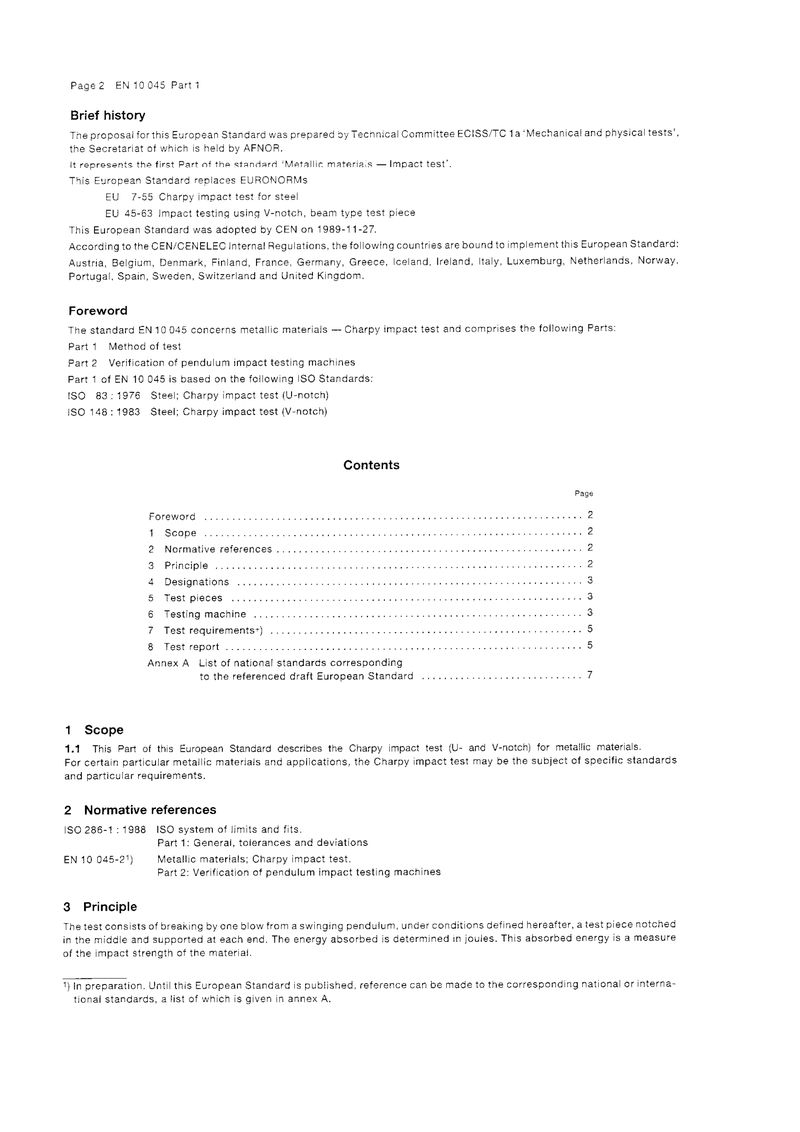
Brief history
The proposal for this European Standard was prepared by Technical Committee ECISS/TC 1a 'Mechanical and physical tests', the Secretariat of which is held by AFNOR.
It represents the first Part of the standard 'Metallic materials — Impact test'.
This European Standard replaces EURONORMs
EU 7-55 Charpy impact test for steel
EU 45-63 Impact testing using V-notch, beam type test piece
This European Standard was adopted by CEN on 1989-11-27.
According to the CEN/CENELEC Internal Regulations, the following countries are bound to implement this European Standard: Austria, Belgium, Denmark, Finland, France, Germany, Greece, Iceland, Ireland, Italy, Luxembourg, Netherlands, Norway, Portugal, Spain, Sweden, Switzerland and United Kingdom.
Foreword
The standard EN 10 045 concerns metallic materials — Charpy impact test and comprises the following Parts:
Part 1 Method of test
Part 2 Verification of pendulum impact testing machines
Part 1 of EN 10 045 is based on the following ISO Standards:
ISO 83 : 1976 Steel; Charpy impact test (U-notch)
ISO 148 : 1983 Steel; Charpy impact test (V-notch)
Contents
| Page | |
| Foreword | 2 |
| 1 Scope | 2 |
| 2 Normative references | 2 |
| 3 Principle | 2 |
| 4 Designations | 3 |
| 5 Test pieces | 3 |
| 6 Testing machine | 3 |
| 7 Test requirements*) | 5 |
| 8 Test report | 5 |
| Annex A List of national standards corresponding to the referenced draft European Standard | 7 |
1 Scope
1.1 This Part of this European Standard describes the Charpy impact test (U- and V-notch) for metallic materials. For certain particular metallic materials and applications, the Charpy impact test may be the subject of specific standards and particular requirements.
2 Normative references
ISO 286-1 : 1988 ISO system of limits and fits.
Part 1: General, tolerances and deviations
EN 10 045-2*) Metallic materials; Charpy impact test.
Part 2: Verification of pendulum impact testing machines
3 Principle
The test consists of breaking by one blow from a swinging pendulum, under conditions defined hereafter, a test piece notched in the middle and supported at each end. The energy absorbed is determined in joules. This absorbed energy is a measure of the impact strength of the material.
1) In preparation. Until this European Standard is published, reference can be made to the corresponding national or international standards, a list of which is given in annex A.
4
Table 1. Designations
| Reference (see fig.1) | Designation | Unit |
|---|---|---|
| 1 | Length of test piece | mm |
| 2 | Height of test piece | mm |
| 3 | Width of test piece | mm |
| 4 | Height below notch | mm |
| 5 | Angle of notch | Degree |
| 6 | Radius of curvature at base of notch | mm |
| 7 | Distance between anvils | mm |
| 8 | Radius of anvils | mm |
| 9 | Angle of taper of each anvil | Degree |
| 10 | Angle of taper of striker | Degree |
| 11 | Radius at tip of striker | mm |
| 12 | Width of striker | mm |
| — | Energy absorbed by breakage, KU or KV | Joule |
4 Designations
The designations applicable to this standard are as indicated in table 1 and figures 1 and 2.
5 Test pieces
5.1 Sampling, number of test pieces and their location shall be as specified in the relevant product standard.
5.2 The standard test piece shall be 55 mm long and of square section with 10 mm sides. In the centre of the length, there shall be a notch. Two types of notch are specified.
a) V-notch of 45°, 2 mm deep, with a 0.25 mm radius of curvature at base of notch.
If standard test pieces cannot be obtained from the material, a reduced section test piece, with a width of 7,5 mm or 5 mm (see table 2) shall be used, the notch being cut in one of the narrow faces.
b) U-notch or keyhole notch, 5 mm deep, with a 1 mm radius of curvature at base of notch.
The test pieces shall be machined all over, except in the case of precision-cast foundry test pieces in which the two faces parallel to the plane of symmetry of the notch may be unmachined.
5.3 The plane of symmetry of the notch shall be perpendicular to the longitudinal axis of the test piece.
5.4 The tolerances on the specified dimensions of the test piece shall be as given in table 2.
5.5 Test pieces of widths other than those shown in table 2, for example, with the unmachined widths equal to the thickness of the product, may be used provided this is permitted in the relevant product standard. Comparison of results, however, is only of significance when made between test pieces of the same form and dimensions.
5.6 Machining shall be carried out in such a way that any alteration of the test piece, e.g. due to cold working or heating, is minimized. The notch shall be carefully prepared so that no grooves, parallel to the base of the notch, are visible to the naked eye.
The test piece may be marked on any face not in contact with the supports or anvils and at a point at least 5 mm from the notch to avoid the effects of cold working due to marking.
6 Testing machine
6.1 The testing machine shall be constructed and installed rigidly and shall be in accordance with European Standard 10 045-2.
The values of the principal characteristics of the testing machine are specified in table 3.
5
Table 2. Tolerances on specified test piece dimensions
| Designation | U-notch test piece | V-notch test piece | ||||
|---|---|---|---|---|---|---|
| Nominal dimension | Machining tolerance | Nominal dimension | Machining tolerance | |||
| ISO symbol 1) | ISO symbol 1) | |||||
| Length | 55 mm | ± 0,60 mm | js15 | 55 mm | ± 0,60 mm | js15 |
| Height | 10 mm | ± 0,11 mm | js13 | 10 mm | ± 0,06 mm | js12 |
| Width: standard test piece | 10 mm | ± 0,11 mm | js13 | 10 mm | ± 0,11 mm | js13 |
| — reduced section test piece | — | — | — | 7,5 mm | ± 0,11 mm | js13 |
| — reduced section test piece | — | — | — | 5 mm | ± 0,06 mm | js12 |
| Angle of notch | — | — | — | 45° | ± 2° | — |
| Height below notch | 5 mm | ± 0,09 mm | js13 | 8 mm | ± 0,06 mm | js12 |
| Radius of curvature at base of notch | 1 mm | ± 0,07 mm | js12 | 0,25 mm | ± 0,025 mm | — |
| Distance of plane of symmetry of notch from ends of test piece 2) | 27,5 mm | ± 0,42 mm | js15 | 27,5 mm | ± 0,42 mm | js15 |
| Angle between plane of symmetry of notch and longitudinal axis of test piece | 90° | ± 2° | — | 90° | ± 2° | — |
| Angle between adjacent longitudinal faces of test piece | 90° | ± 2° | — | 90° | ± 2° | — |
1) In accordance with ISO 286-1.
2) For machines with automatic positioning of the test piece, it is recommended that the tolerance be taken as ±0,165 mm instead of ±0,42 mm.
Table 3. Characteristics of testing machine
| Reference (see fig.1) | Designation | Value |
|---|---|---|
| 7 | Distance between anvils | (40 +0,2 -0) mm |
| 8 | Radius of anvils | (1 +0,5 -0) mm |
| 9 | Angle of taper of each anvil | 11° ± 1° |
| 10 | Angle of taper of striker | 30° ± 1° |
| 11 | Radius at tip of striker | (2 +0,5 -0) mm |
| 12 | Maximum width of striker | 18 mm |
| — | Speed of striker at instant of impact | 5 to 5,5 m/s 1) |
| — | Angle between the support and the anvil | 90° ± 0,1° |
1) For machines manufactured prior to 1983, a speed of 4,5 m/s to 7 m/s is permissible by agreement.
6.2 Standard test conditions
Standard test conditions shall correspond to a nominal machine energy of (300 ± 10) J and the use of a test piece of standard dimensions*). The reported absorbed energy under these conditions shall be designated by the symbols:
- KU for a U-notch test piece
- KV for a V-notch test piece
6
预览内容由文件识别整理,表格、公式及文字请以原始文件为准。
原文图片预览
PAGE IMAGES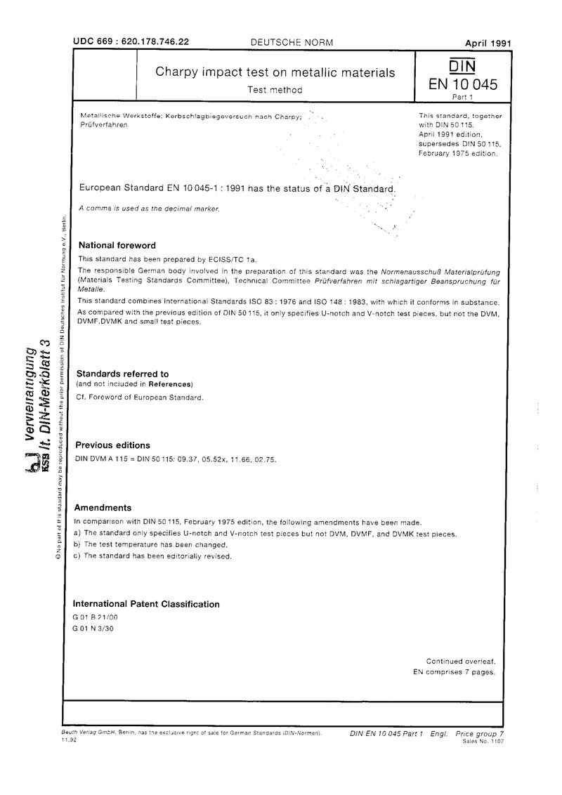
下载标准文件
DIN EN 10045
英语 · PDF · 6 页 · 178.11 KB