标准信息
STANDARD INFORMATION- 标准编号
- DIN 2617
- 所属分类
- DIN 德国标准
- 发布机构
- DIN
- 版本年份
- 1997
- 文件语言
- 英语
- 文件格式
- 文件页数
- 6 页
- 文件大小
- 1.14 MB
中文名称为参考译名,文件语言以原文为准。
· 更新:
标准简介
OVERVIEW中文简介
该标准规定了用于与管道对焊连接的钢制封头(Caps)的尺寸、公差及标记方法。它涵盖了不同公称尺寸(DN 15至DN 1200)下,符合ISO 4200系列1外径的封头壁厚系列及高度参数。
English summary
This standard specifies the dimensions, tolerances, and designation of steel caps intended to be butt-welded to pipes. It covers wall thickness series and heights for various nominal sizes (DN 15 to DN 1200) corresponding to ISO 4200 Series 1 pipe outside diameters.
以上为根据文件整理的内容简介。
相关标签
标准内容预览
DOCUMENT PREVIEWSteel butt-welding pipe fittings
Caps
Formstücke zum Einschweißen; Kappen; Maße
Supersedes June 1964 edition.
In keeping with current practice in standards published by the International Organization for Standardization (ISO), a comma has been used throughout as the decimal marker.
Dimensions in mm
1 Field of application
This standard specifies steel caps that are intended to be butt welded to pipes and that are rated for the same internal pressure as pipes having a wall thickness as specified in table 1 (cf. clause 4).
2 Dimensions and designation
Dished portion
Cylindrical portion
r1 ≈ 0,8 da
r2 ≈ 0,154 da
s2 ≥ s1
Designation of a cap in accordance with this standard, having an outside diameter, da, equal to 88,9 mm and a wall thickness, s1, equal to 2,3 mm, made from material belonging to material group C as in DIN 2609 (C):
Cap DIN 2617 – 88,9 × 2,3 – C
Continued on pages 2 and 3
1
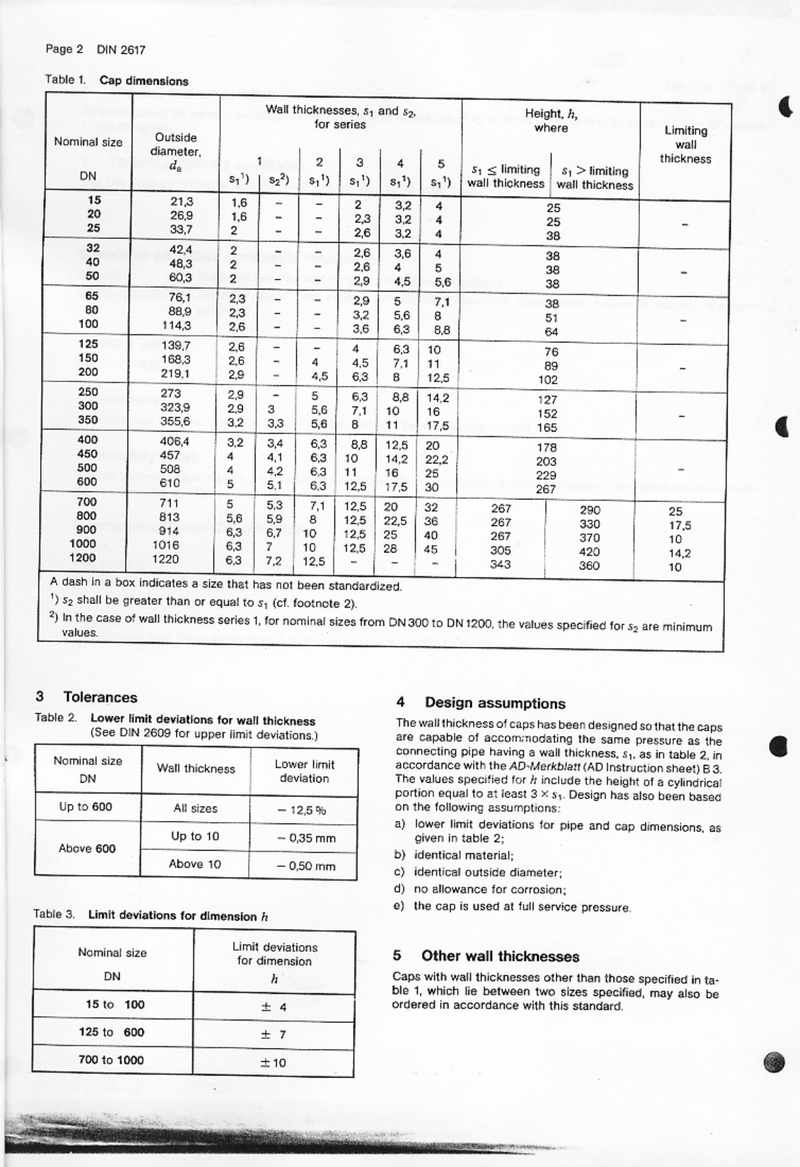
Table 1. Cap dimensions
| Nominal size DN | Outside diameter, de | Wall thicknesses, s1 and s2, for series | Height, h, where | Limiting wall thickness | ||||||
|---|---|---|---|---|---|---|---|---|---|---|
| 1 s11) |
s22) | 2 s11) |
3 s11) |
4 s11) |
5 s11) |
s1 ≤ limiting wall thickness | s1 > limiting wall thickness | |||
| 15 | 21,3 | 1,6 | - | - | 2 | 3,2 | 4 | 25 | - | |
| 20 | 26,9 | 1,6 | - | - | 2,3 | 3,2 | 4 | 25 | ||
| 25 | 33,7 | 2 | - | - | 2,6 | 3,2 | 4 | 38 | ||
| 32 | 42,4 | 2 | - | - | 2,6 | 3,6 | 4 | 38 | - | |
| 40 | 48,3 | 2 | - | - | 2,6 | 4 | 5 | 38 | ||
| 50 | 60,3 | 2 | - | - | 2,9 | 4,5 | 5,6 | 38 | ||
| 65 | 76,1 | 2,3 | - | - | 2,9 | 5 | 7,1 | 38 | - | |
| 80 | 88,9 | 2,3 | - | - | 3,2 | 5,6 | 8 | 51 | ||
| 100 | 114,3 | 2,6 | - | - | 3,6 | 6,3 | 8,8 | 64 | ||
| 125 | 139,7 | 2,6 | - | - | 4 | 6,3 | 10 | 76 | - | |
| 150 | 168,3 | 2,6 | - | 4 | 4,5 | 7,1 | 11 | 89 | ||
| 200 | 219,1 | 2,9 | - | 4,5 | 6,3 | 8 | 12,5 | 102 | ||
| 250 | 273 | 2,9 | - | 5 | 6,3 | 8,8 | 14,2 | 127 | - | |
| 300 | 323,9 | 2,9 | 3 | 5,6 | 7,1 | 10 | 16 | 152 | ||
| 350 | 355,6 | 3,2 | 3,3 | 5,6 | 8 | 11 | 17,5 | 165 | ||
| 400 | 406,4 | 3,2 | 3,4 | 6,3 | 8,8 | 12,5 | 20 | 178 | - | |
| 450 | 457 | 4 | 4,1 | 6,3 | 10 | 14,2 | 22,2 | 203 | ||
| 500 | 508 | 4 | 4,2 | 6,3 | 11 | 16 | 25 | 229 | ||
| 600 | 610 | 5 | 5,1 | 6,3 | 12,5 | 17,5 | 30 | 267 | ||
| 700 | 711 | 5 | 5,3 | 7,1 | 12,5 | 20 | 32 | 267 | 290 | 25 |
| 800 | 813 | 5,6 | 5,9 | 8 | 12,5 | 22,5 | 36 | 267 | 330 | 17,5 |
| 900 | 914 | 6,3 | 6,7 | 10 | 12,5 | 25 | 40 | 267 | 370 | 10 |
| 1000 | 1016 | 6,3 | 7 | 10 | 12,5 | 28 | 45 | 305 | 420 | 14,2 |
| 1200 | 1220 | 6,3 | 7,2 | 12,5 | - | - | - | 343 | 360 | 10 |
A dash in a box indicates a size that has not been standardized.
1) s2 shall be greater than or equal to s1 (cf. footnote 2).
2) In the case of wall thickness series 1, for nominal sizes from DN 300 to DN 1200, the values specified for s2 are minimum values.
3 TolerancesTable 2. Lower limit deviations for wall thickness
Table 3. Limit deviations for dimension h
|
4 Design assumptionsThe wall thickness of caps has been designed so that the caps are capable of accommodating the same pressure as the connecting pipe having a wall thickness, s1, as in table 2, in accordance with the AD-Merkblatt (AD Instruction sheet) B 3. The values specified for h include the height of a cylindrical portion equal to at least 3 × s1. Design has also been based on the following assumptions: a) lower limit deviations for pipe and cap dimensions, as given in table 2; b) identical material; c) identical outside diameter; d) no allowance for corrosion; e) the cap is used at full service pressure. 5 Other wall thicknessesCaps with wall thicknesses other than those specified in table 1, which lie between two sizes specified, may also be ordered in accordance with this standard. |
2
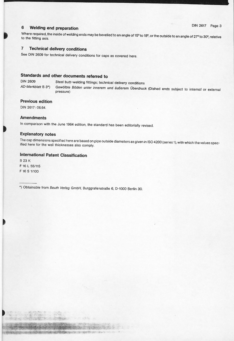
6 Welding end preparation
Where required, the inside of welding ends may be bevelled to an angle of 15° to 18°, or the outside to an angle of 27° to 30°, relative to the fitting axis.
7 Technical delivery conditions
See DIN 2609 for technical delivery conditions for caps as covered here.
Standards and other documents referred to
| DIN 2609 | Steel butt-welding fittings; technical delivery conditions |
| AD-Merkblatt B 3*) | Gewölbte Böden unter innerem und äußerem Überdruck (Dished ends subject to internal or external pressure) |
Previous edition
DIN 2617: 06.64.
Amendments
In comparison with the June 1964 edition, the standard has been editorially revised.
Explanatory notes
The cap dimensions specified here are based on pipe outside diameters as given in ISO 4200 (series 1), with which the values specified here for the wall thicknesses also comply.
International Patent Classification
B 23 K
F 16 L 55/115
F 16 S 1/100
*) Obtainable from Beuth Verlag GmbH, Burggrafenstraße 6, D-1000 Berlin 30.
3
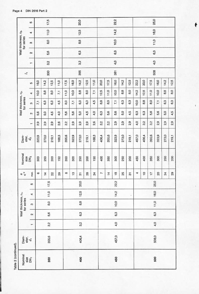
Table 2 (continued).
| Nominal size DN1 | Diameter, d1 | Wall thickness, s1, for series | αxo max. | Nominal size DN2 | Diameter, d2 | Wall thickness, s2, for series | l1 | Wall thickness, s3, for series | ||||||||||||
|---|---|---|---|---|---|---|---|---|---|---|---|---|---|---|---|---|---|---|---|---|
| 1 | 2 | 3 | 4 | 5 | 1 | 2 | 3 | 4 | 5 | 1 | 2 | 3 | 4 | 5 | ||||||
| 350 | 355,6 | 3,2 | 5,6 | 8,0 | 11,0 | 17,5 | 6 | 300 | 323,9 | 2,9 | 5,6 | 7,1 | 10,0 | 16,0 | 330 | 3,2 | 5,6 | 8,0 | 11,0 | 17,5 |
| 14 | 250 | 273,0 | 2,9 | 5,0 | 6,3 | 8,8 | 14,2 | |||||||||||||
| 22 | 200 | 219,1 | 2,9 | 4,5 | 6,3 | 8,0 | 12,5 | |||||||||||||
| 29 | 150 | 168,3 | 2,6 | 4,0 | 4,5 | 7,1 | 11,0 | |||||||||||||
| 8 | 350 | 355,6 | 3,2 | 5,6 | 8,0 | 11,0 | 17,5 | |||||||||||||
| 400 | 406,4 | 3,2 | 6,3 | 8,8 | 12,5 | 20,0 | 13 | 300 | 323,9 | 2,9 | 5,6 | 7,1 | 10,0 | 16,0 | 355 | 3,2 | 6,3 | 8,8 | 12,5 | 20,0 |
| 21 | 250 | 273,0 | 2,9 | 5,0 | 6,3 | 8,8 | 14,2 | |||||||||||||
| 28 | 200 | 219,1 | 2,9 | 4,5 | 6,3 | 8,0 | 12,5 | |||||||||||||
| 34 | 150 | 168,3 | 2,6 | 4,0 | 4,5 | 7,1 | 11,0 | |||||||||||||
| 7 | 400 | 406,4 | 3,2 | 6,3 | 8,8 | 12,5 | 20,0 | |||||||||||||
| 450 | 457,0 | 4,0 | 6,3 | 10,0 | 14,2 | 22,2 | 14 | 350 | 355,6 | 3,2 | 5,6 | 8,0 | 11,0 | 17,5 | 381 | 4,0 | 6,3 | 10,0 | 14,2 | 22,2 |
| 18 | 300 | 323,9 | 2,9 | 5,6 | 7,1 | 10,0 | 16,0 | |||||||||||||
| 25 | 250 | 273,0 | 2,9 | 5,0 | 6,3 | 8,8 | 14,2 | |||||||||||||
| 31 | 200 | 219,1 | 2,9 | 4,5 | 6,3 | 8,0 | 12,5 | |||||||||||||
| 4 | 450 | 457,0 | 4,0 | 6,3 | 10,0 | 14,2 | 22,2 | |||||||||||||
| 500 | 508,0 | 4,0 | 6,3 | 11,0 | 16,0 | 25,0 | 10 | 400 | 406,4 | 3,2 | 6,3 | 8,8 | 12,5 | 20,0 | 508 | 4,0 | 6,3 | 11,0 | 16,0 | 25,0 |
| 17 | 350 | 355,6 | 3,2 | 5,6 | 8,0 | 11,0 | 17,5 | |||||||||||||
| 20 | 300 | 323,9 | 2,9 | 5,6 | 7,1 | 10,0 | 16,0 | |||||||||||||
| 24 | 250 | 273,0 | 2,9 | 5,0 | 6,3 | 8,8 | 14,2 | |||||||||||||
| 29 | 200 | 219,1 | 2,9 | 4,5 | 6,3 | 8,0 | 12,5 | |||||||||||||
4
Table 2 (continued).
| Nominal size DN1 | Diameter, d1 | Wall thickness, s1, for series | αmax ° | Nominal size DN2 | Diameter, d2 | Wall thickness, s2, for series | l1 | Wall thickness, s3, for series | ||||||||||||
|---|---|---|---|---|---|---|---|---|---|---|---|---|---|---|---|---|---|---|---|---|
| 1 | 2 | 3 | 4 | 5 | 1 | 2 | 3 | 4 | 5 | 1 | 2 | 3 | 4 | 5 | ||||||
| 600 | 610,0 | 5,0 | 6,3 | 12,5 | 17,5 | 30,0 | 10 | 500 | 508,0 | 4,0 | 6,3 | 11,0 | 16,0 | 25,0 | 508 | 5,0 | 6,3 | 12,5 | 17,5 | 30 |
| 15 | 450 | 457,0 | 4,0 | 6,3 | 10,0 | 14,2 | 22,2 | |||||||||||||
| 21 | 400 | 406,4 | 3,2 | 6,3 | 8,8 | 12,5 | 20,0 | |||||||||||||
| 26 | 350 | 355,6 | 3,2 | 5,6 | 8,0 | 11,0 | 17,5 | |||||||||||||
| 29 | 300 | 323,9 | 2,9 | 5,6 | 7,1 | 10,0 | 16,0 | |||||||||||||
| 33 | 250 | 273,0 | 2,9 | 5,0 | 6,3 | 8,8 | 14,2 | |||||||||||||
| 700 | 711,0 | 5,0 | 7,1 | 12,5 | 20,0 | 32,0 | 10 | 600 | 610,0 | 5,0 | 6,3 | 12,5 | 17,5 | 30,0 | 610 | 5,0 | 7,1 | 12,5 | 20,0 | 32 |
| 15 | 500 | 508,0 | 4,0 | 6,3 | 11,0 | 16,0 | 25,0 | |||||||||||||
| 20 | 450 | 457,0 | 4,0 | 6,3 | 10,0 | 14,2 | 22,2 | |||||||||||||
| 25 | 400 | 406,4 | 3,2 | 6,3 | 8,8 | 12,5 | 20,0 | |||||||||||||
| 30 | 350 | 355,6 | 3,2 | 5,6 | 8,0 | 11,0 | 17,5 | |||||||||||||
| 33 | 300 | 323,9 | 2,9 | 5,6 | 7,1 | 10,0 | 16,0 | |||||||||||||
| 800 | 813,0 | 5,6 | 8,0 | 12,5 | 22,2 | 36,0 | 10 | 700 | 711,0 | 5,0 | 7,1 | 12,5 | 20,0 | 32,0 | 610 | 5,6 | 8,0 | 12,5 | 22,2 | 36 |
| 15 | 600 | 610,0 | 5,0 | 6,3 | 12,5 | 17,5 | 30,0 | |||||||||||||
| 20 | 500 | 508,0 | 4,0 | 6,3 | 11,0 | 16,0 | 25,0 | |||||||||||||
| 25 | 450 | 457,0 | 4,0 | 6,3 | 10,0 | 14,2 | 22,2 | |||||||||||||
| 30 | 400 | 406,4 | 3,2 | 6,3 | 8,8 | 12,5 | 20,0 | |||||||||||||
| 35 | 350 | 355,6 | 3,2 | 5,6 | 8,0 | 11,0 | 17,5 | |||||||||||||
| 900 | 914,0 | 6,3 | 10,0 | 12,5 | 25,0 | 40,0 | 10 | 800 | 813,0 | 5,6 | 8,0 | 12,5 | 22,2 | 36,0 | 610 | 6,3 | 10,0 | 12,5 | 25,0 | 40 |
| 15 | 700 | 711,0 | 5,0 | 7,1 | 12,5 | 20,0 | 32,0 | |||||||||||||
| 20 | 600 | 610,0 | 5,0 | 6,3 | 12,5 | 17,5 | 30,0 | |||||||||||||
| 25 | 500 | 508,0 | 4,0 | 6,3 | 11,0 | 16,0 | 25,0 | |||||||||||||
| 30 | 450 | 457,0 | 4,0 | 6,3 | 10,0 | 14,2 | 22,2 | |||||||||||||
| 35 | 400 | 406,4 | 3,2 | 6,3 | 8,8 | 12,5 | 20,0 | |||||||||||||
5
Table 2 (concluded).
| Nominal size DN1 | Diameter, d1 | Wall thickness, s1, for series | αmax | Nominal size DN2 | Diameter, d2 | Wall thickness, s2, for series | l1 | Wall thickness, s3, for series | ||||||||||||
|---|---|---|---|---|---|---|---|---|---|---|---|---|---|---|---|---|---|---|---|---|
| 1 | 2 | 3 | 4 | 5 | 1 | 2 | 3 | 4 | 5 | 1 | 2 | 3 | 4 | 5 | ||||||
| 1000 | 1016,0 | 6,3 | 10,0 | 12,5 | 28,0 | 45,0 | 10 | 900 | 914,0 | 6,3 | 10,0 | 12,5 | 25,0 | 40,0 | 610 | 6,3 | ||||
| 15 | 800 | 813,0 | 5,6 | 8,0 | 12,5 | 22,2 | 36,0 | |||||||||||||
| 20 | 700 | 711,0 | 5,0 | 7,1 | 12,5 | 20,0 | 32,0 | 10,0 | 12,5 | 28,0 | 45 | |||||||||
| 25 | 600 | 610,0 | 5,0 | 6,3 | 12,5 | 17,5 | 30,0 | 6,4 | 10,2 | 12,5 | ||||||||||
| 30 | 500 | 508,0 | 4,0 | 6,3 | 11,0 | 16,0 | 25,0 | |||||||||||||
| 35 | 450 | 457,0 | 4,0 | 6,3 | 10,0 | 14,2 | 22,2 | |||||||||||||
| 1200 | 1220,0 | 6,3 | 12,5 | - | - | - | 10 | 1000 | 1016,0 | 6,3 | 10,0 | - | - | - | 711 | 6,3 | 1,25 | - | - | - |
| 15 | 900 | 914,0 | 6,3 | 10,0 | - | - | - | |||||||||||||
| 20 | 800 | 813,0 | 5,6 | 8,0 | - | - | - | 6,4 | 12,5 | - | - | - | ||||||||
| 25 | 700 | 711,0 | 5,0 | 7,1 | - | - | - | |||||||||||||
| 30 | 600 | 610,0 | 5,0 | 6,3 | - | - | - | 6,6 | 12,5 | - | - | - | ||||||||
A dash in a box indicates a size that has not been standardized.
6
预览内容由文件识别整理,表格、公式及文字请以原始文件为准。
原文图片预览
PAGE IMAGES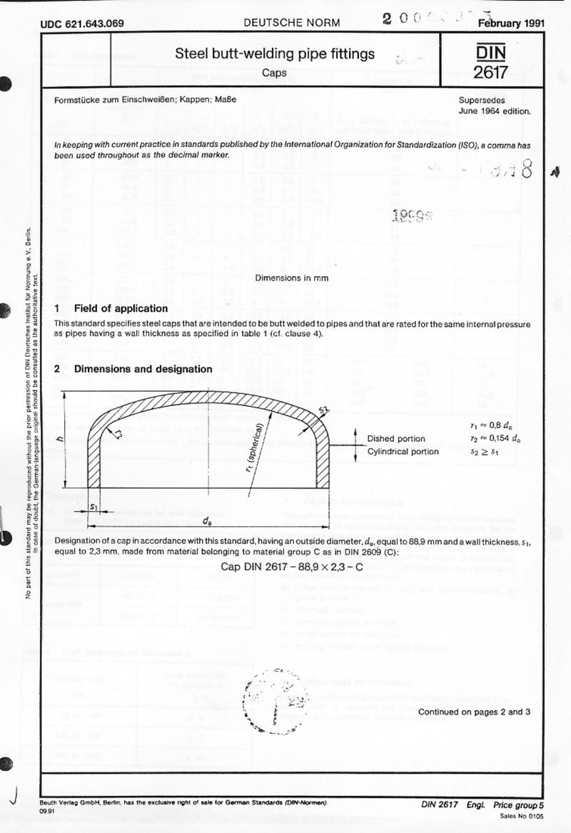
下载标准文件
DIN 2617
英语 · PDF · 6 页 · 1.14 MB