DIN 2614(1)
球墨铸铁管和钢管及管件的水泥砂浆内衬 应用、要求和测试
DIN 2614(1)
Cement mortar linings for ductile iron and steel pipes and fittings Application, requirements and testing
标准信息
STANDARD INFORMATION- 标准编号
- DIN 2614(1)
- 所属分类
- DIN 德国标准
- 发布机构
- DIN
- 版本年份
- 2019
- 文件语言
- 英语
- 文件格式
- 文件页数
- 6 页
- 文件大小
- 5.86 MB
中文名称为参考译名,文件语言以原文为准。
· 更新:
标准简介
OVERVIEW中文简介
该标准规定了球墨铸铁管和钢管及其管件的水泥砂浆内衬的要求、测试方法以及施工工艺。它涵盖了内衬材料(如水泥、骨料、聚合物改性砂浆)、施工过程(离心喷涂、手工涂抹)及养护条件,旨在改善管道的水力特性并防止腐蚀。
English summary
This standard specifies the requirements, testing methods, and application procedures for cement mortar linings on ductile iron and steel pipes and fittings. It covers material specifications, lining processes such as centrifugal spraying and manual application, and curing conditions to improve hydraulic properties and prevent corrosion in water pipelines.
以上为根据文件整理的内容简介。
相关标签
标准内容预览
DOCUMENT PREVIEWCement mortar linings for ductile iron and steel pipes and fittings
Application, requirements and testing
Zementmörtelauskleidungen für Gußrohre, Stahlrohre und Formstücke; Verfahren, Anforderungen, Prüfungen
In keeping with current practice in standards published by the International Organization for Standardization (ISO), a comma has been used throughout as the decimal marker.
This standard has been jointly prepared by DIN Deutsches Institut für Normung e. V. and DVGW Deutscher Verein des Gas- und Wasserfaches e. V. (German Gas and Water Engineers' Association). It has been adopted into the DVGW Codes of practice on gas and water, and supersedes the DVGW-Arbeitsblätter (DVGW Codes of practice) W 342 and W 344.
Dimensions in mm
Contents
| Page | Page |
|---|---|
| 1 Scope and field of application | 2 |
| 2 Designation and ordering | 2 |
| 2.1 Standard designation | 2 |
| 2.2 Order details | 2 |
| 2.2.1 Essential order details | 2 |
| 2.2.2 Optional order details | 2 |
| 3 Concepts | 2 |
| 3.1 Plasticizers | 2 |
| 3.2 Polymers | 2 |
| 3.3 Mixing ratio | 2 |
| 3.4 Repair mortar | 2 |
| 3.5 Additions | 2 |
| 4 Lining processes and curing | 3 |
| 4.1 Lining processes | 3 |
| 4.1.1 Centrifugal lining | 3 |
| 4.1.2 Centrifugal spraying | 3 |
| 4.1.3 Manual lining | 3 |
| 4.2 Preparation for curing | 3 |
| 4.2.1 Curing of lining that is not polymer modified | 3 |
| 4.2.1.1 Curing at the storage site at ambient temperature | 3 |
| 4.2.1.2 Curing under moist/warm conditions | 3 |
| 4.2.1.3 Curing in draught-free, closed spaces | 3 |
| 4.2.2 Curing of polymer modified linings | 3 |
| 4.3 Repairs, storage and transport | 3 |
| 4.3.1 Repairs to linings | 3 |
| 4.3.2 Storage and transport | 3 |
| 5 Types of cement mortar | 3 |
| 5.1 General | 3 |
| 5.2 Mortar containing plasticizers | 4 |
| 5.3 Polymer modified mortar | 4 |
| 5.4 Mortar for water supply pipes | 4 |
| 5.5 Repair mortar | 4 |
| 6 Requirements | 4 |
| 6.1 General | 4 |
| 6.2 Substrate | 5 |
| 6.3 Constituents | 5 |
| 6.3.1 Cement | 5 |
| 6.3.2 Aggregates | 5 |
| 6.3.2.1 Grading | 5 |
| 6.3.2.2 Cleanliness of aggregates | 5 |
| 6.3.3 Mixing water | 5 |
| 6.3.4 Additions | 5 |
| 6.3.5 Admixtures | 5 |
| 6.3.5.1 Plasticizers | 5 |
| 6.3.5.2 Polymers | 5 |
| 6.3.5.2.1 Resistance to saponification | 5 |
| 6.3.5.2.2 Behaviour on exposure to microorganisms | 5 |
| 6.4 Fresh mortar | 5 |
| 6.4.1 Mixing ratio | 5 |
| 6.4.2 Water/cement ratio | 5 |
| 6.5 Cured lining | 6 |
| 6.5.1 Surface condition | 6 |
| 6.5.2 Design of pipe ends | 6 |
| 6.5.2.1 Socket ends, flanged ends and threaded ends | 6 |
| 6.5.2.2 Ends for welding | 6 |
| 6.5.3 Lining thickness | 7 |
| 6.5.4 Lining of pipes conveying salt water, brine or other waters that are aggressive to concrete | 7 |
| 6.6 Properties of cement mortar | 8 |
| 6.6.1 Compressive strength and flexural strength | 8 |
| 6.6.2 Corrosion resistance | 8 |
| 7 Testing | 8 |
| 7.1 General | 8 |
| 7.2 Substrate | 9 |
| 7.3 Cement mortar constituents | 9 |
| 7.3.1 Cement | 9 |
| 7.3.2 Aggregates | 9 |
| 7.3.2.1 Grading | 9 |
| 7.3.2.2 Cleanliness of aggregates | 9 |
| 7.3.3 Mixing water | 9 |
| 7.3.4 Additions | 9 |
| 7.3.5 Admixtures | 9 |
| 7.3.5.1 Plasticizers | 9 |
| 7.3.5.2 Polymers | 9 |
| 7.3.5.2.1 Resistance to saponification | 9 |
| 7.3.5.2.2 Behaviour on exposure to microorganisms | 9 |
| 7.4 Mixing ratio and water/cement ratio of fresh mortar | 9 |
| 7.4.1 Method of determination | 9 |
| 7.4.2 Sampling | 9 |
| 7.4.3 Determination of sand content | 9 |
| 7.4.4 Determination of water content | 9 |
| 7.4.4.1 Drying to constant mass | 9 |
| 7.4.4.2 Distillation method | 9 |
| 7.5 Quality of cured lining | 10 |
| 7.5.1 Surface condition | 10 |
| 7.5.1.1 Irregular surface | 10 |
| 7.5.1.2 Cracks | 10 |
| 7.5.1.3 Structure | 10 |
| 7.5.1.4 Hydraulic roughness | 10 |
| 7.5.2 Design of pipe ends | 10 |
| 7.5.3 Lining thickness | 10 |
| 7.6 Compressive strength, flexural strength and corrosion resistance of mortar | 10 |
| 7.6.1 Compressive strength and flexural strength | 10 |
| 7.6.2 Corrosion resistance | 10 |
| Standards and other documents referred to | 11 |
| Other relevant standards and documents | 12 |
| Explanatory notes | 13 |
Continued on pages 2 to 14
1
Page 2 DIN 2614
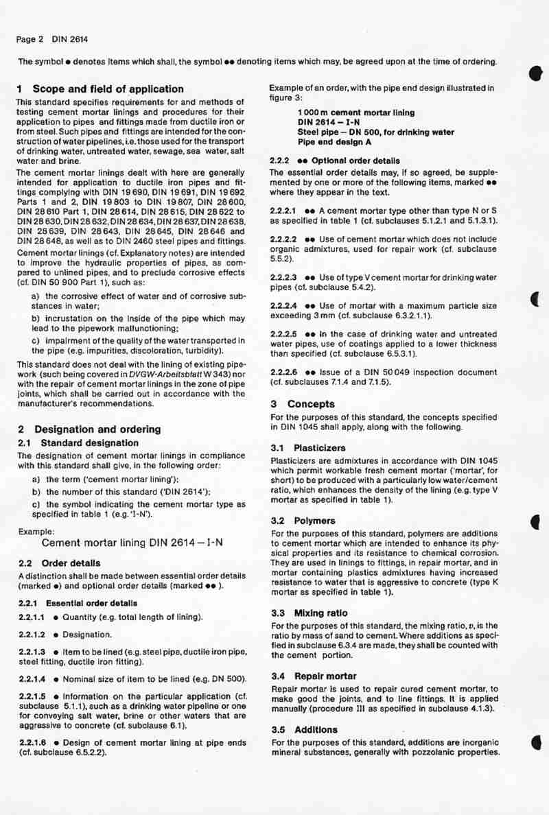
The symbol ● denotes items which shall, the symbol ●● denoting items which may, be agreed upon at the time of ordering.
1 Scope and field of application
This standard specifies requirements for and methods of testing cement mortar linings and procedures for their application to pipes and fittings made from ductile iron or from steel. Such pipes and fittings are intended for the construction of water pipelines, i.e. those used for the transport of drinking water, untreated water, sewage, sea water, salt water and brine.
The cement mortar linings dealt with here are generally intended for application to ductile iron pipes and fittings complying with DIN 19 690, DIN 19 691, DIN 19 692 Parts 1 and 2, DIN 19 803 to DIN 19 807, DIN 28 600, DIN 28 610 Part 1, DIN 28 614, DIN 28 615, DIN 28 622 to DIN 28 630, DIN 28 632, DIN 28 634, DIN 28 637, DIN 28 638, DIN 28 639, DIN 28 643, DIN 28 645, DIN 28 646 and DIN 28 648, as well as to DIN 2460 steel pipes and fittings. Cement mortar linings (cf. Explanatory notes) are intended to improve the hydraulic properties of pipes, as compared to unlined pipes, and to preclude corrosive effects (cf. DIN 50 900 Part 1), such as:
a) the corrosive effect of water and of corrosive substances in water;
b) incrustation on the inside of the pipe which may lead to the pipework malfunctioning;
c) impairment of the quality of the water transported in the pipe (e.g. impurities, discoloration, turbidity).
This standard does not deal with the lining of existing pipework (such being covered in DVGW-Arbeitsblatt W 343) nor with the repair of cement mortar linings in the zone of pipe joints, which shall be carried out in accordance with the manufacturer's recommendations.
2 Designation and ordering
2.1 Standard designation
The designation of cement mortar linings in compliance with this standard shall give, in the following order:
a) the term ('cement mortar lining');
b) the number of this standard ('DIN 2614');
c) the symbol indicating the cement mortar type as specified in table 1 (e.g. 'I-N').
Example:
Cement mortar lining DIN 2614—I-N
2.2 Order details
A distinction shall be made between essential order details (marked ●) and optional order details (marked ●●).
2.2.1 Essential order details
2.2.1.1 ● Quantity (e.g. total length of lining).
2.2.1.2 ● Designation.
2.2.1.3 ● Item to be lined (e.g. steel pipe, ductile iron pipe, steel fitting, ductile iron fitting).
2.2.1.4 ● Nominal size of item to be lined (e.g. DN 500).
2.2.1.5 ● Information on the particular application (cf. subclause 5.1.1), such as a drinking water pipeline or one for conveying salt water, brine or other waters that are aggressive to concrete (cf. subclause 6.1).
2.2.1.6 ● Design of cement mortar lining at pipe ends (cf. subclause 6.5.2.2).
Example of an order, with the pipe end design illustrated in figure 3:
1 000 m cement mortar lining
DIN 2614—I-N
Steel pipe—DN 500, for drinking water
Pipe end design A
2.2.2 ●● Optional order details
The essential order details may, if so agreed, be supplemented by one or more of the following items, marked ●● where they appear in the text.
2.2.2.1 ●● A cement mortar type other than type N or S as specified in table 1 (cf. subclauses 5.1.2.1 and 5.1.3.1).
2.2.2.2 ●● Use of cement mortar which does not include organic admixtures, used for repair work (cf. subclause 5.5.2).
2.2.2.3 ●● Use of type V cement mortar for drinking water pipes (cf. subclause 5.4.2).
2.2.2.4 ●● Use of mortar with a maximum particle size exceeding 3 mm (cf. subclause 6.3.2.1.1).
2.2.2.5 ●● In the case of drinking water and untreated water pipes, use of coatings applied to a lower thickness than specified (cf. subclause 6.5.3.1).
2.2.2.6 ●● Issue of a DIN 50 049 inspection document (cf. subclauses 7.1.4 and 7.1.5).
3 Concepts
For the purposes of this standard, the concepts specified in DIN 1045 shall apply, along with the following.
3.1 Plasticizers
Plasticizers are admixtures in accordance with DIN 1045 which permit workable fresh cement mortar ('mortar', for short) to be produced with a particularly low water/cement ratio, which enhances the density of the lining (e.g. type V mortar as specified in table 1).
3.2 Polymers
For the purposes of this standard, polymers are additions to cement mortar which are intended to enhance its physical properties and its resistance to chemical corrosion. They are used in linings to fittings, in repair mortar, and in mortar containing plastics admixtures having increased resistance to water that is aggressive to concrete (type K mortar as specified in table 1).
3.3 Mixing ratio
For the purposes of this standard, the mixing ratio, v, is the ratio by mass of sand to cement. Where additions as specified in subclause 6.3.4 are made, they shall be counted with the cement portion.
3.4 Repair mortar
Repair mortar is used to repair cured cement mortar, to make good the joints, and to line fittings. It is applied manually (procedure III as specified in subclause 4.1.3).
3.5 Additions
For the purposes of this standard, additions are inorganic mineral substances, generally with pozzolanic properties.
2
4 Lining processes and curing
4.1 Lining processes
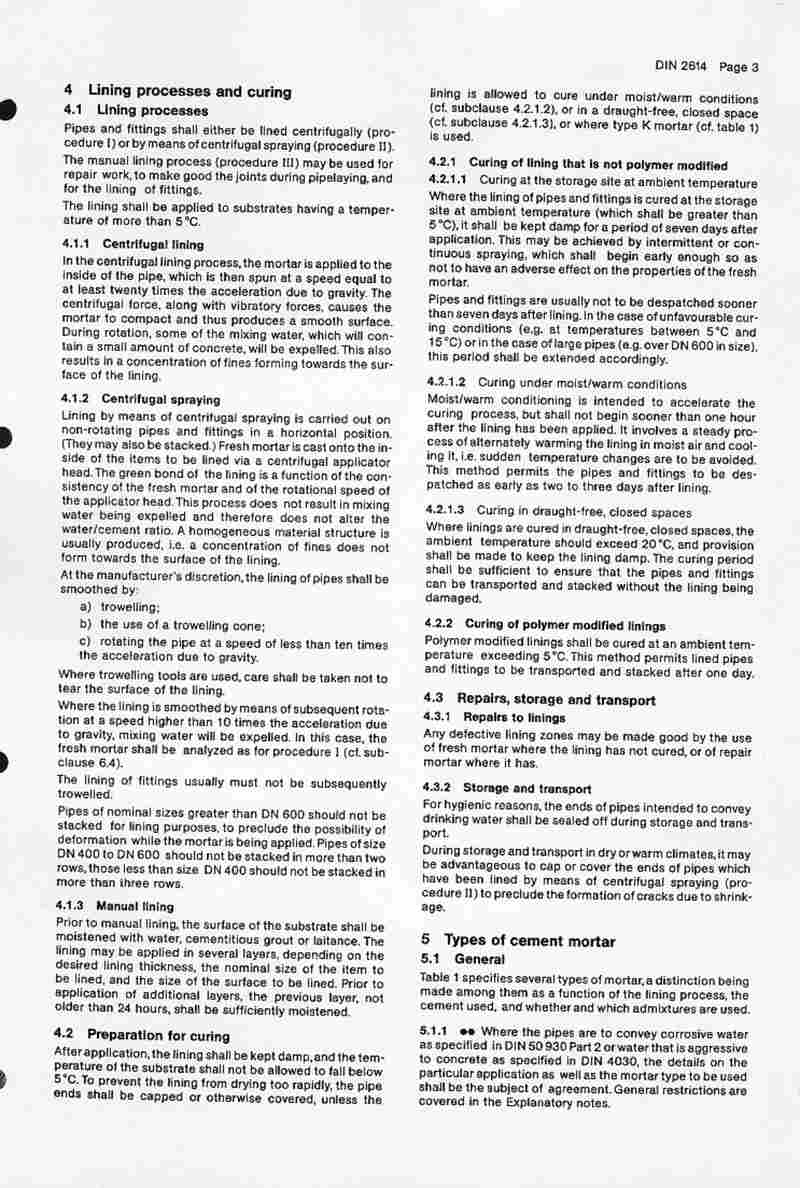
Pipes and fittings shall either be lined centrifugally (procedure I) or by means of centrifugal spraying (procedure II). The manual lining process (procedure III) may be used for repair work, to make good the joints during pipelaying, and for the lining of fittings.
The lining shall be applied to substrates having a temperature of more than 5°C.
4.1.1 Centrifugal lining
In the centrifugal lining process, the mortar is applied to the inside of the pipe, which is then spun at a speed equal to at least twenty times the acceleration due to gravity. The centrifugal force, along with vibratory forces, causes the mortar to compact and thus produces a smooth surface. During rotation, some of the mixing water, which will contain a small amount of concrete, will be expelled. This also results in a concentration of fines forming towards the surface of the lining.
4.1.2 Centrifugal spraying
Lining by means of centrifugal spraying is carried out on non-rotating pipes and fittings in a horizontal position. (They may also be stacked.) Fresh mortar is cast onto the inside of the items to be lined via a centrifugal applicator head. The green bond of the lining is a function of the consistency of the fresh mortar and of the rotational speed of the applicator head. This process does not result in mixing water being expelled and therefore does not alter the water/cement ratio. A homogeneous material structure is usually produced, i.e. a concentration of fines does not form towards the surface of the lining.
At the manufacturer's discretion, the lining of pipes shall be smoothed by:
a) trowelling;
b) the use of a trowelling cone;
c) rotating the pipe at a speed of less than ten times the acceleration due to gravity.
Where trowelling tools are used, care shall be taken not to tear the surface of the lining.
Where the lining is smoothed by means of subsequent rotation at a speed higher than 10 times the acceleration due to gravity, mixing water will be expelled. In this case, the fresh mortar shall be analyzed as for procedure I (cf. subclause 6.4).
The lining of fittings usually must not be subsequently trowelled.
Pipes of nominal sizes greater than DN 600 should not be stacked for lining purposes, to preclude the possibility of deformation while the mortar is being applied. Pipes of size DN 400 to DN 600 should not be stacked in more than two rows, those less than size DN 400 should not be stacked in more than three rows.
4.1.3 Manual lining
Prior to manual lining, the surface of the substrate shall be moistened with water, cementitious grout or laitance. The lining may be applied in several layers, depending on the desired lining thickness, the nominal size of the item to be lined, and the size of the surface to be lined. Prior to application of additional layers, the previous layer, not older than 24 hours, shall be sufficiently moistened.
4.2 Preparation for curing
After application, the lining shall be kept damp, and the temperature of the substrate shall not be allowed to fall below 5°C. To prevent the lining from drying too rapidly, the pipe ends shall be capped or otherwise covered, unless the lining is allowed to cure under moist/warm conditions (cf. subclause 4.2.1.2), or in a draught-free, closed space (cf. subclause 4.2.1.3), or where type K mortar (cf. table 1) is used.
4.2.1 Curing of lining that is not polymer modified
4.2.1.1 Curing at the storage site at ambient temperature
Where the lining of pipes and fittings is cured at the storage site at ambient temperature (which shall be greater than 5°C), it shall be kept damp for a period of seven days after application. This may be achieved by intermittent or continuous spraying, which shall begin early enough so as not to have an adverse effect on the properties of the fresh mortar.
Pipes and fittings are usually not to be dispatched sooner than seven days after lining. In the case of unfavourable curing conditions (e.g. at temperatures between 5°C and 15°C) or in the case of large pipes (e.g. over DN 600 in size), this period shall be extended accordingly.
4.2.1.2 Curing under moist/warm conditions
Moist/warm conditioning is intended to accelerate the curing process, but shall not begin sooner than one hour after the lining has been applied. It involves a steady process of alternately warming the lining in moist air and cooling it, i.e. sudden temperature changes are to be avoided. This method permits the pipes and fittings to be dispatched as early as two to three days after lining.
4.2.1.3 Curing in draught-free, closed spaces
Where linings are cured in draught-free, closed spaces, the ambient temperature should exceed 20°C, and provision shall be made to keep the lining damp. The curing period shall be sufficient to ensure that the pipes and fittings can be transported and stacked without the lining being damaged.
4.2.2 Curing of polymer modified linings
Polymer modified linings shall be cured at an ambient temperature exceeding 5°C. This method permits lined pipes and fittings to be transported and stacked after one day.
4.3 Repairs, storage and transport
4.3.1 Repairs to linings
Any defective lining zones may be made good by the use of fresh mortar where the lining has not cured, or of repair mortar where it has.
4.3.2 Storage and transport
For hygienic reasons, the ends of pipes intended to convey drinking water shall be sealed off during storage and transport.
During storage and transport in dry or warm climates, it may be advantageous to cap or cover the ends of pipes which have been lined by means of centrifugal spraying (procedure II) to preclude the formation of cracks due to shrinkage.
5 Types of cement mortar
5.1 General
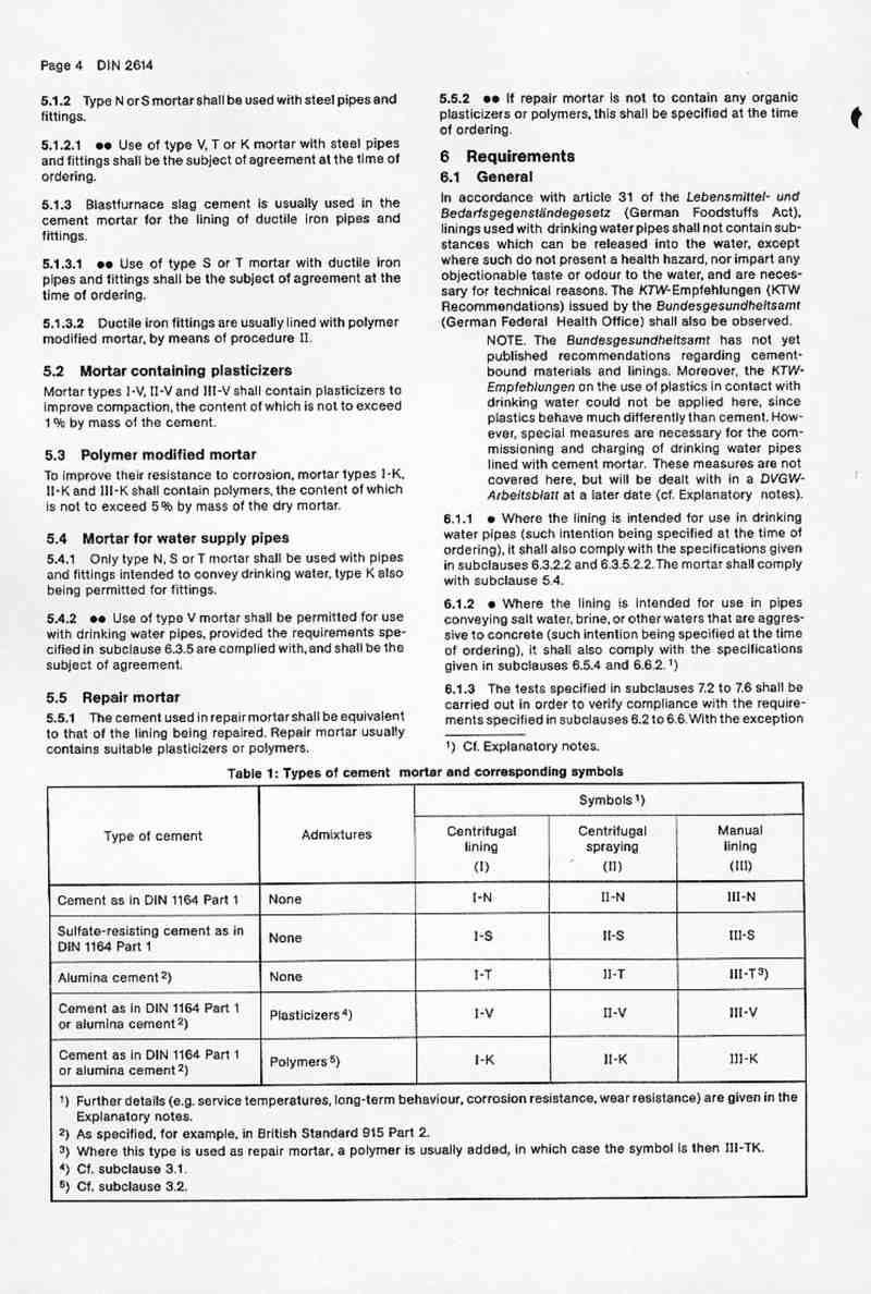
Table 1 specifies several types of mortar, a distinction being made among them as a function of the lining process, the cement used, and whether and which admixtures are used.
5.1.1 Where the pipes are to convey corrosive water
as specified in DIN 50 930 Part 2 or water that is aggressive to concrete as specified in DIN 4030, the details on the particular application as well as the mortar type to be used shall be the subject of agreement. General restrictions are covered in the Explanatory notes.
3
5.1.2 Type N or S mortar shall be used with steel pipes and fittings
5.1.2 Type N or S mortar shall be used with steel pipes and fittings.
5.1.2.1 Use of type V, T or K mortar with steel pipes and fittings shall be the subject of agreement at the time of ordering.
5.1.3 Blastfurnace slag cement is usually used in the cement mortar for the lining of ductile iron pipes and fittings.
5.1.3.1 Use of type S or T mortar with ductile iron pipes and fittings shall be the subject of agreement at the time of ordering.
5.1.3.2 Ductile iron fittings are usually lined with polymer modified mortar, by means of procedure II.
5.2 Mortar containing plasticizers
Mortar types I-V, II-V and III-V shall contain plasticizers to improve compaction, the content of which is not to exceed 1% by mass of the cement.
5.3 Polymer modified mortar
To improve their resistance to corrosion, mortar types I-K, II-K and III-K shall contain polymers, the content of which is not to exceed 5% by mass of the dry mortar.
5.4 Mortar for water supply pipes
5.4.1 Only type N, S or T mortar shall be used with pipes and fittings intended to convey drinking water, type K also being permitted for fittings.
5.4.2 Use of type V mortar shall be permitted for use with drinking water pipes, provided the requirements specified in subclause 6.3.5 are complied with, and shall be the subject of agreement.
5.5 Repair mortar
5.5.1 The cement used in repair mortar shall be equivalent to that of the lining being repaired. Repair mortar usually contains suitable plasticizers or polymers.
5.5.2 If repair mortar is not to contain any organic plasticizers or polymers, this shall be specified at the time of ordering.
6 Requirements
6.1 General
In accordance with article 31 of the Lebensmittel- und Bedarfsgegenständegesetz (German Foodstuffs Act), linings used with drinking water pipes shall not contain substances which can be released into the water, except where such do not present a health hazard, nor impart any objectionable taste or odour to the water, and are necessary for technical reasons. The K7W-Empfehlungen (K7W Recommendations) issued by the Bundesgesundheitsamt (German Federal Health Office) shall also be observed.
NOTE. The Bundesgesundheitsamt has not yet published recommendations regarding cement-bound materials and linings. Moreover, the K7W-Empfehlungen on the use of plastics in contact with drinking water could not be applied here, since plastics behave much differently than cement. However, special measures are necessary for the commissioning and charging of drinking water pipes lined with cement mortar. These measures are not covered here, but will be dealt with in a DVGW-Arbeitsblatt at a later date (cf. Explanatory notes).
6.1.1 Where the lining is intended for use in drinking water pipes (such intention being specified at the time of ordering), it shall also comply with the specifications given in subclauses 6.3.2.2 and 6.3.5.2.2. The mortar shall comply with subclause 5.4.
6.1.2 Where the lining is intended for use in pipes conveying salt water, brine, or other waters that are aggressive to concrete (such intention being specified at the time of ordering), it shall also comply with the specifications given in subclauses 6.5.4 and 6.6.2. 1)
6.1.3 The tests specified in subclauses 7.2 to 7.6 shall be carried out in order to verify compliance with the requirements specified in subclauses 6.2 to 6.6. With the exception
1) Cf. Explanatory notes.
| Type of cement | Admixtures | Symbols 1) | ||
|---|---|---|---|---|
| Centrifugal lining (I) | Centrifugal spraying (II) | Manual lining (III) | ||
| Cement as in DIN 1164 Part 1 | None | I-N | II-N | III-N |
| Sulfate-resisting cement as in DIN 1164 Part 1 | None | I-S | II-S | III-S |
| Alumina cement 2) | None | I-T | II-T | III-T 3) |
| Cement as in DIN 1164 Part 1 or alumina cement 2) | Plasticizers 4) | I-V | II-V | III-V |
| Cement as in DIN 1164 Part 1 or alumina cement 2) | Polymers 5) | I-K | II-K | III-K |
1) Further details (e.g. service temperatures, long-term behaviour, corrosion resistance, wear resistance) are given in the Explanatory notes.
2) As specified, for example, in British Standard 915 Part 2.
3) Where this type is used as repair mortar, a polymer is usually added, in which case the symbol is then III-TK.
4) Cf. subclause 3.1.
5) Cf. subclause 3.2.
4
6.2 Substrate
All surfaces to be lined with cement mortar shall be free from rust, scale, loose weld beads, grease, oil and other impurities. In the case of steel pipes and fittings, standard preparation grade St 2 as defined in DIN 55928 Part 4, for example, shall be deemed sufficient. Slight rust, such as that which inevitably results from hydraulic testing, is permitted.
6.3 Constituents
6.3.1 Cement
The cement used shall be in compliance with the materials standards listed in table 1, as a function of mortar type, and reported to the client.
6.3.2 Aggregates
Aggregates shall consist of clean, natural, coarse or split quartz sand and shall comply with the requirements specified in DIN 4226 Part 1.
6.3.2.1 Grading
The fines content, as determined by sieve analysis using a sieving medium of 0,125 mm complying with ISO 3310 Part 1, shall not exceed 10%. The maximum particle size shall not exceed 50% of the minimum coating thickness and, as a departure from DIN 4226 Part 1, should not exceed
a) 3 mm for mortar applied by procedure I;
b) 2 mm for mortar applied by procedure II;
c) 1,5 mm for mortar applied by procedure III.
6.3.2.1.1 It shall be agreed at the time of ordering whether the maximum particle size of aggregates used in mortar for the lining of steel pipes may exceed 3 mm.
6.3.2.2 Cleanliness of aggregates
In the case of linings intended for use in drinking water pipes, when tested in accordance with subclause 7.3.2.2, the extract in demineralized water shall not exceed 0,1 g per kg of sand, and that in NaOH, 0,3 g per kg of sand.
6.3.3 Mixing water
The mixing water shall be in compliance with DIN 1045, be potable or of comparable quality, have a conductivity of less than 2000 μS/cm and a KMnO4 consumption of less than 10 mg/l.
6.3.4 Additions
Any additions used shall be in compliance with DIN 1045. Pozzolana may be used only up to a content of 10%, non-pozzolanic additions, up to a content of 3%, by mass of the cement. The manufacturer shall inform the client of the type and amount of any additions used.
6.3.5 Admixtures
Types V and K mortar and repair mortar (cf. table 1) shall contain either plasticizers or polymers.
6.3.5.1 Plasticizers
Plasticizers shall be in compliance with DIN 1045, and satisfy the requirements specified in subclauses 6.3.5.2.1 and 6.3.5.2.2.
6.3.5.2 Polymers
Polymers shall comply with the requirements specified in subclauses 6.3.5.2.1 and 6.3.5.2.2.
6.3.5.2.1 Resistance to saponification
When tested in accordance with subclause 7.3.5.2.1, the consumption of 0,1 mol/l HCl shall be greater than 45 ml.
6.3.5.2.2 Behaviour on exposure to microorganisms
Linings intended for use in drinking water pipes shall satisfy the requirements specified in DVGW-Arbeitsblatt W 270 with regard to their behaviour on exposure to microorganisms.
6.4 Fresh mortar
The requirements specified for fresh mortar refer to the condition of the mortar upon application. For testing purposes, samples shall be taken immediately before the material is to be applied. All measuring equipment used shall permit measurements to be made to an accuracy of ± 3%.
The specified amounts of all constituents shall be thoroughly mixed by means of an electric mixer, this type of mixer not being necessary in the case of repair mortar.
6.4.1 Mixing ratio
The maximum value of the sand/cement mixing ratio, v, shall be calculated using equation (1) in subclause 7.4.1 and be in compliance with table 2.
| Cement mortar type (cf. clause 5) | Procedure I | Procedure II | Procedure III |
|---|---|---|---|
| Maximum | 2,5 | 2,0 | 2,0 |
When tested in accordance with subclause 7.4, one single value may exceed the specified maximum value by 0,1. However, the mean determined for each pipe size, per batch, shall not exceed the maximum value specified.
6.4.2 Water/cement ratio
The degree of compaction of cement mortar linings is a function of the method used to manufacture the mortar. The water/cement ratio, w (cf. equation (2)), is a major factor influencing the degree of compaction, and shall be determined in accordance with subclause 7.4.1. Other factors of influence include the water requirement of the cement, the mixing ratio, and the particle size distribution of the aggregate. Figure 1 illustrates the design water/cement ratio as a function of the mixing ratio, where Portland cement or alumina cement is used, and with aggregates having the grading specified in subclause 6.3.2.1. In figure 1:
a) line A represents mortar types II-N, II-S, III-N and III-S where Portland cement is used, and types II-T and III-T;
b) line B represents mortar types II-V, III-V, II-K and III-K where Portland cement is used, and type III-TK;
c) line C represents mortar types I-N and I-S where Portland cement is used, and type I-T;
d) line D represents mortar types I-V and I-K where Portland cement is used.
The actual mean values determined for w shall not exceed the design values illustrated in figure 1. However, in the following cases, the design values given shall be increased by 0,02:
a) mortar incorporating blastfurnace slag cement;
b) mortar incorporating aggregates with a low particle size (i.e. up to about 1 mm).
Single values of w shall not exceed 0,40 where v is less than 2,0, nor 0,42 where v is greater than 2,0.
5
6.5 Cured lining
Figure 1: Design water/cement ratio as a function of mixing ratio (cf. subclause 6.4.2) where Portland cement or alumina cement is used in cement mortar
6.5.1 Surface condition
The surface of cured cement mortar linings shall be as smooth as possible, any irregularities being not more than 1 mm in depth when tested in accordance with subclause 7.5.1.1. Localized irregularities in the lining of fittings shall be not more than 2,5 mm in depth.
The hydraulic roughness, ks, shall not exceed 0,1 mm.
During the curing process, cracks may form in the lining due to pipe expansion or mortar shrinkage, but will close again upon contact with water. When tested in accordance with subclause 7.5.1.2, single cracks shall be permitted, provided they are not wider than 2,5 mm and do not have an adverse effect on the convexity of the lining.
The cured lining shall not exhibit any chipping nor any loose sand particles. Protruding, firmly embedded grains of sand shall be permitted.
When tested in accordance with subclause 7.5.1.3, linings applied by means of procedure I shall have a layer of fines not exceeding one-fourth the total lining thickness in the case of linings thicker than 8 mm or, in the case of those up to 8 mm thick, not exceeding 2 mm.
NOTE: During transport and pipelaying, it shall be ensured that any cracks in the lining do not cause it to become displaced. Any zones or cracks wider than 1,5 mm which form as a result of expansion in service shall be repaired, unless it can be assumed that they will close on exposure to water and heal by an autogenous process.
6.5.2 Design of pipe ends
6.5.2.1 Socket ends, flanged ends and threaded ends
Pipes provided with ring-seal socket ends, of either the push-in type or those intended for welding, shall be lined up to the bottom of the socket, their counterparts being lined up to the end of the spigot. Any ring-seal grooves incorporated in the end shall not be lined.
The lining shall extend to the end of pipes provided with flanged or threaded ends.
It shall be permitted for the lining to be tapered slightly toward the end of the pipe, the tapered zone covering a distance of not more than 50 mm.
In the case of flanged socket pieces and collars, the lining shall be applied in such a way that it is possible to slip the fittings onto the pipe barrel. This may involve a lower lining thickness than that specified in subclause 6.5.3, but shall be permitted.
6.5.2.2 Ends for welding
Pipes of size DN 600 or more intended for exposure to vehicular traffic are normally provided with butt-welded pipe fittings as illustrated in figure 2. The lining shall not be applied along a length of about 25 mm as measured from the pipe end; this zone shall be lined with repair mortar after the joint has been made.
Figure 2: Butt-welded joint in steel pipe intended for exposure to vehicular traffic (simplified)
Irrespective of whether pipes and fittings are intended for exposure to vehicular traffic, the method of end preparation illustrated in figure 3 may be used. The lining shall extend to the pipe end, and then cut back 3 to 5 mm to comply with either lining type A or B.
Figure 3: Butt-welded joint in steel pipe, irrespective of exposure to vehicular traffic (simplified)
Where lining type A is selected, it is recommended that the lining thickness be a minimum of 8 mm.
NOTE: Butt-welded joints which are not subsequently made good shall only be permitted in pipes conveying water which acts in such a way that the sealing and closing of the gap in service is ensured. Such joints are not permitted for pipes conveying salt water or brine.
Figure 4: Spigot/socket joint for welding
6
预览内容由文件识别整理,表格、公式及文字请以原始文件为准。
原文图片预览
PAGE IMAGES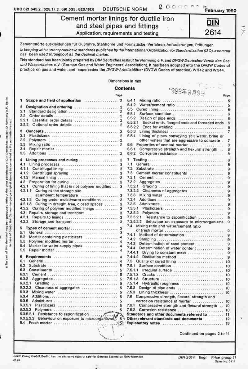
下载标准文件
DIN 2614(1)
英语 · PDF · 6 页 · 5.86 MB