din-74-1(1)
沉头螺钉用沉孔(不含DIN EN 27721头螺钉)
din-74-1(1)
Countersinks for countersunk head screws (except screws with DIN EN 27721 head)
标准信息
STANDARD INFORMATION- 标准编号
- din-74-1(1)
- 所属分类
- DIN 德国标准
- 发布机构
- DIN
- 版本年份
- 1997
- 文件语言
- 英语
- 文件格式
- 文件页数
- 6 页
- 文件大小
- 12.87 MB
中文名称为参考译名,文件语言以原文为准。
· 更新:
标准简介
OVERVIEW中文简介
该标准规定了用于沉头螺钉的沉孔尺寸、标记方法及图纸表示法。它适用于木螺钉、结构钢螺栓及内六角沉头螺钉等特定类型的紧固件,排除了ISO 7721头螺钉的沉孔(参见DIN 66)。
English summary
This standard specifies the dimensions, designation, and drawing indications for countersinks used with countersunk head screws. It applies to wood screws, structural steel bolts, and hexagon socket countersunk head screws, excluding those with ISO 7721 heads which are covered by DIN 66.
以上为根据文件整理的内容简介。
相关标签
标准内容预览
DOCUMENT PREVIEWCountersinks for countersunk head screws (except screws with DIN EN 27721 head)
| ICS 21.060.01 | Supersedes December 1980 edition. |
Senkungen für Senkschrauben (ausgenommen Senkschrauben mit Köpfen nach DIN EN 27721)
In keeping with current practice in standards published by the International Organization for Standardization (ISO), a comma has been used throughout as the decimal marker.
Foreword
This standard has been prepared by Technical Committee Fachgrundnormen of the Normenausschuss Mechanische Verbindungselemente (Fasteners Standards Committee).
The revision of this standard reflects the developments that have taken place since the last edition was published in December 1980, a large number of national standards on countersunk head screws for which countersinks were specified in the former edition of this standard having since been superseded by ISO Standards and countersinks for countersunk head screws with DIN EN 27721 heads now being specified in DIN 66. As a result, this standard now only specifies countersinks for those screws for which national standards still exist.
Amendments
This standard differs from the December 1980 edition as follows.
a) Countersinks for countersunk head screws with ISO 7721 head as well as countersinks for metric screws, self-cutting screws, thread-grooving screws, tapping screws, and type A fine series wood screws are no longer included (cf. DIN 66).
b) Type F countersinks have been modified to fit hexagon socket countersunk head screws as in DIN EN ISO 10642.
Previous editions
DIN 74-1: 1971-01, 1980-12.
All dimensions are in millimetres.
1 Scope
This standard specifies dimensions and designation of countersinks for countersunk heads screws as in DIN 95, DIN 97, DIN 7969, DIN 7995, DIN 7997, and DIN EN ISO 10642.
NOTE: Countersinks for countersunk head screws with DIN EN 27721 head are specified in DIN 66.
Continued on pages 2 to 4.
Translation by DIN-Sprachendienst.
In case of doubt, the German-language original should be consulted as the authoritative text.
1
2 Normative references
This standard incorporates, by dated or undated reference, provisions from other publications. These normative references are cited at the appropriate places in the text, and the titles of the publications are listed below. For dated references, subsequent amendments to or revisions of any of these publications apply to this standard only when incorporated in it by amendment or revision. For undated references, the latest edition of the publication referred to applies.
| DIN 66 | Countersinks for countersunk head screws with ISO 7721 common head style |
| DIN 95 | Slotted raised countersunk (oval) head wood screws |
| DIN 97 | Slotted countersunk (flat) head wood screws |
| DIN 7969 | Slotted countersunk head screws for structural steel bolting for supply with or without nut |
| DIN 7995 | Cross recessed raised countersunk head wood screws |
| DIN 7997 | Cross recessed countersunk head wood screws |
| DIN EN 20273 | Fasteners – Clearance holes for bolts and screws (ISO 273 : 1979) |
| DIN EN 27721 | Countersunk head screws – Head configuration and gauging (ISO 7721 : 1983) |
| DIN EN ISO 10642 | Hexagon socket countersunk head screws (ISO 10642 : 1997) |
3 Dimensions and designation
Countersink dimensions shall be as given in figures 1 to 3 and tables 1 to 3.
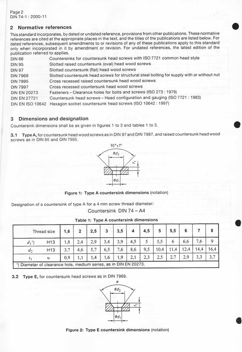
3.1 Type A, for countersunk head wood screws as in DIN 97 and DIN 7997, and raised countersunk head wood screws as in DIN 95 and DIN 7995.
Figure 1: Type A countersink dimensions (notation)
Designation of a countersink of type A for a 4 mm screw thread diameter:
Countersink DIN 74 – A4
| Thread size | 1,6 | 2 | 2,5 | 3 | 3,5 | 4 | 4,5 | 5 | 5,5 | 6 | 7 | 8 |
|---|---|---|---|---|---|---|---|---|---|---|---|---|
| d11) H13 | 1,8 | 2,4 | 2,9 | 3,4 | 3,9 | 4,5 | 5 | 5,5 | 6 | 6,6 | 7,6 | 9 |
| d2 H13 | 3,7 | 4,6 | 5,7 | 6,5 | 7,6 | 8,6 | 9,5 | 10,4 | 11,4 | 12,4 | 14,4 | 16,4 |
| t1 ≈ | 0,9 | 1,1 | 1,4 | 1,6 | 1,9 | 2,1 | 2,3 | 2,5 | 2,7 | 2,9 | 3,3 | 3,7 |
| 1) Diameter of clearance hole, medium series, as in DIN EN 20273. | ||||||||||||
3.2 Type E, for countersunk head screws as in DIN 7969.
Figure 2: Type E countersink dimensions (notation)
2
Designation of a countersink of type E for a 12 mm screw thread diameter
Countersink DIN 74 – E12
| Thread size | 10 | 12 | 16 | 20 | 22 | 24 |
|---|---|---|---|---|---|---|
| d11) H13 | 10,5 | 13 | 17 | 21 | 23 | 25 |
| d2 H13 | 19 | 24 | 31 | 34 | 37 | 40 |
| t1 ≈ | 5,5 | 7 | 9 | 11,5 | 12 | 13 |
| α ±1° | 75° | 60° | ||||
| 1) Diameter of clearance hole, medium series, as in DIN EN 20273. | ||||||
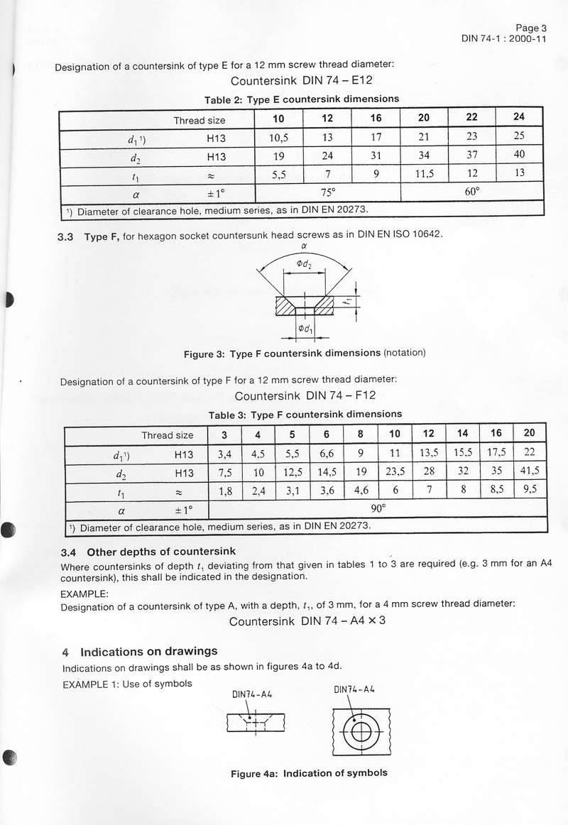
3.3 Type F, for hexagon socket countersunk head screws as in DIN EN ISO 10642.
Figure 3: Type F countersink dimensions (notation)
Designation of a countersink of type F for a 12 mm screw thread diameter:
Countersink DIN 74 – F12
| Thread size | 3 | 4 | 5 | 6 | 8 | 10 | 12 | 14 | 16 | 20 |
|---|---|---|---|---|---|---|---|---|---|---|
| d11) H13 | 3,4 | 4,5 | 5,5 | 6,6 | 9 | 11 | 13,5 | 15,5 | 17,5 | 22 |
| d2 H13 | 7,5 | 10 | 12,5 | 14,5 | 19 | 23,5 | 28 | 32 | 35 | 41,5 |
| t1 ≈ | 1,8 | 2,4 | 3,1 | 3,6 | 4,6 | 6 | 7 | 8 | 8,5 | 9,5 |
| α ±1° | 90° | |||||||||
| 1) Diameter of clearance hole, medium series, as in DIN EN 20273. | ||||||||||
3.4 Other depths of countersink
Where countersinks of depth t1, deviating from that given in tables 1 to 3 are required (e.g. 3 mm for an A4 countersink), this shall be indicated in the designation.
EXAMPLE:
Designation of a countersink of type A, with a depth, t1, of 3 mm, for a 4 mm screw thread diameter:
Countersink DIN 74 – A4 × 3
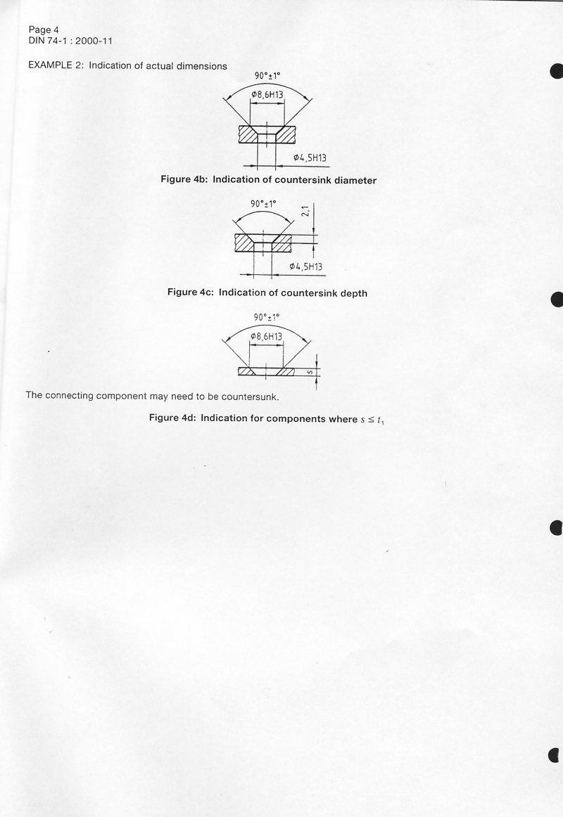
4 Indications on drawings
Indications on drawings shall be as shown in figures 4a to 4d.
EXAMPLE 1: Use of symbols
Figure 4a: Indication of symbols
3
EXAMPLE 2: Indication of actual dimensions
Figure 4b: Indication of countersink diameter
Figure 4c: Indication of countersink depth
The connecting component may need to be countersunk.
Figure 4d: Indication for components where s ≤ t1
4
3.9 Content of harmful salts causing efflorescence
Bricks shall be free from harmful salts leading to structural damage in the bricks or plaster. Bricks shall be deemed to have passed the test for harmful salts if the test described in subclause 6.5, carried out on loose bricks, shows that the proportion by mass of magnesium sulfate (MgSO4) does not exceed 0,12 %.
4 Designation
The following symbols shall be used for the various types of brick:
LLz lightweight horizontally perforated brick
LLp lightweight horizontally perforated brick panel
The sequence of elements used when designating lightweight horizontally perforated bricks shall be term, DIN number, type of brick (symbol), compressive strength class, apparent brick density class and format symbol as given in table 6.
Example of designation:
Designation of a lightweight horizontally perforated brick (LLz) of compressive strength class 12, apparent brick density class 0,9, length l = 240 mm, width b = 175 mm and height h = 113 mm (3 DF):
Brick DIN 105 — LLz 12 — 0,9 — 3 DF
The sequence of elements used when designating lightweight horizontally perforated brick panels shall be DIN number, type of brick (symbol), apparent brick density class and format symbol as given in table 7.
Example of designation:
Designation of a lightweight horizontally perforated brick panel (LLp) of apparent brick density class 0,6, length l = 330 mm, height h = 238 mm and thickness s = 80 mm (80 s):
Brick DIN 105 — LLp 0,6 — 80 s
If lightweight horizontally perforated brick panels are produced with differing length or height, these dimensions shall also be stated in the designation.
Example of designation:
Designation of a lightweight horizontally perforated brick panel (LLp) of apparent brick density class 0,6, length l = 495 mm, height h = 320 mm and thickness s = 60 mm:
Brick DIN 105 — LLp 0,6 — 495 × 320 × 60
5 Marking
All bricks shall be provided with a works mark (manufacturer's mark) and the symbol identifying the brick type (LLz or LLp).
Lightweight horizontally perforated bricks ready for dispatch shall additionally be marked on one stretcher face with a colour coding stripe not less than 20 mm in width, indicating the compressive strength class (see table 8) and details of their apparent brick density class.
An indication of the apparent density class is considered adequate for lightweight horizontally perforated brick panels.
It shall be deemed sufficient if one brick is marked for up to 200 lightweight horizontally perforated bricks not less than 10 DF and for up to 50 lightweight horizontally perforated brick panels.
| Format symbol DF (thin format) | Dimensions | ||
|---|---|---|---|
| l | b | h | |
| NF | 240 | 115 | 71 |
| 2 DF | 240 | 115 | 113 |
| 3 DF | 240 | 175 | 113 |
| 8 DF | 240 | 240 | 238 |
| 12 DF | 365 | 240 | 238 |
| 16 DF | 490 | 240 | 238 |
| 10 DF | 240 | 300 | 238 |
| 15 DF | 365 | 300 | 238 |
| 20 DF | 490 | 300 | 238 |
| Format symbols | Dimensions | ||
|---|---|---|---|
| l | h | s | |
| 40 s | 330 | 238 | 40 |
| 50 s | 330 | 238 | 50 |
| 60 s | 330 | 238 | 60 |
| 70 s | 330 | 238 | 70 |
| 80 s | 330 | 238 | 80 |
| 100 s | 330 | 238 | 100 |
| 115 s | 330 | 238 | 115 |
| Compressive strength class | Colour |
|---|---|
| 2 | Green |
| 4 | Blue |
| 6 | Red |
| 12 | No marking |
5
6 Testing
6.1 Shape, dimensions, perforation
In accordance with DIN 105 Part 1.
A measuring rule or a gauge board with a millimetre scale is sufficient for measuring the length of lightweight horizontally perforated brick panels with dimensions exceeding 495 mm.
The deflection shall also be determined for lightweight horizontally perforated brick panels as illustrated in figure 5. In this determination, the panel shall be pressed on a longitudinal face or width against a smooth surface. Deviations from straightness shall be determined using a measuring wedge and stated to the nearest whole millimetre.
6.2 Apparent brick density
In accordance with DIN 105 Part 1.
6.3 Compressive strength
In accordance with DIN 105 Part 1.
Lightweight horizontally perforated bricks, including standard format bricks, shall be tested as whole bricks. Form factors shall not be applied.
6.4 Bending strength
The bending strength of lightweight horizontally perforated brick panels shall be determined on 5 air-dried samples.
Each panel shall be tested lying flat. The panel shall be placed on two supports so that it can move and stressed in the middle parallel to the supports by means of a 20 mm wide mandrel. The distance between supports shall equal the length of the panel minus 50 mm. The load shall be increased steadily at a rate of approximately 10 N per second.
6.5 Expansive particles and water-soluble salts
In accordance with DIN 105 Part 1.
7 Inspection
7.1 General
See DIN 105 Part 1.
7.2 Internal control
In accordance with DIN 105 Part 1.
7.3 Third party inspection
In accordance with DIN 105 Part 1.
The inspection of lightweight horizontally perforated brick panels shall include the bending strength test instead of the compressive strength test and the determination of deflection.
8 Delivery note
In accordance with DIN 105 Part 1.
Standards referred to
DIN 105 Part 1 Clay bricks; solid bricks and vertically perforated bricks
International Patent Classification
E 04 C 1-00
6
预览内容由文件识别整理,表格、公式及文字请以原始文件为准。
原文图片预览
PAGE IMAGES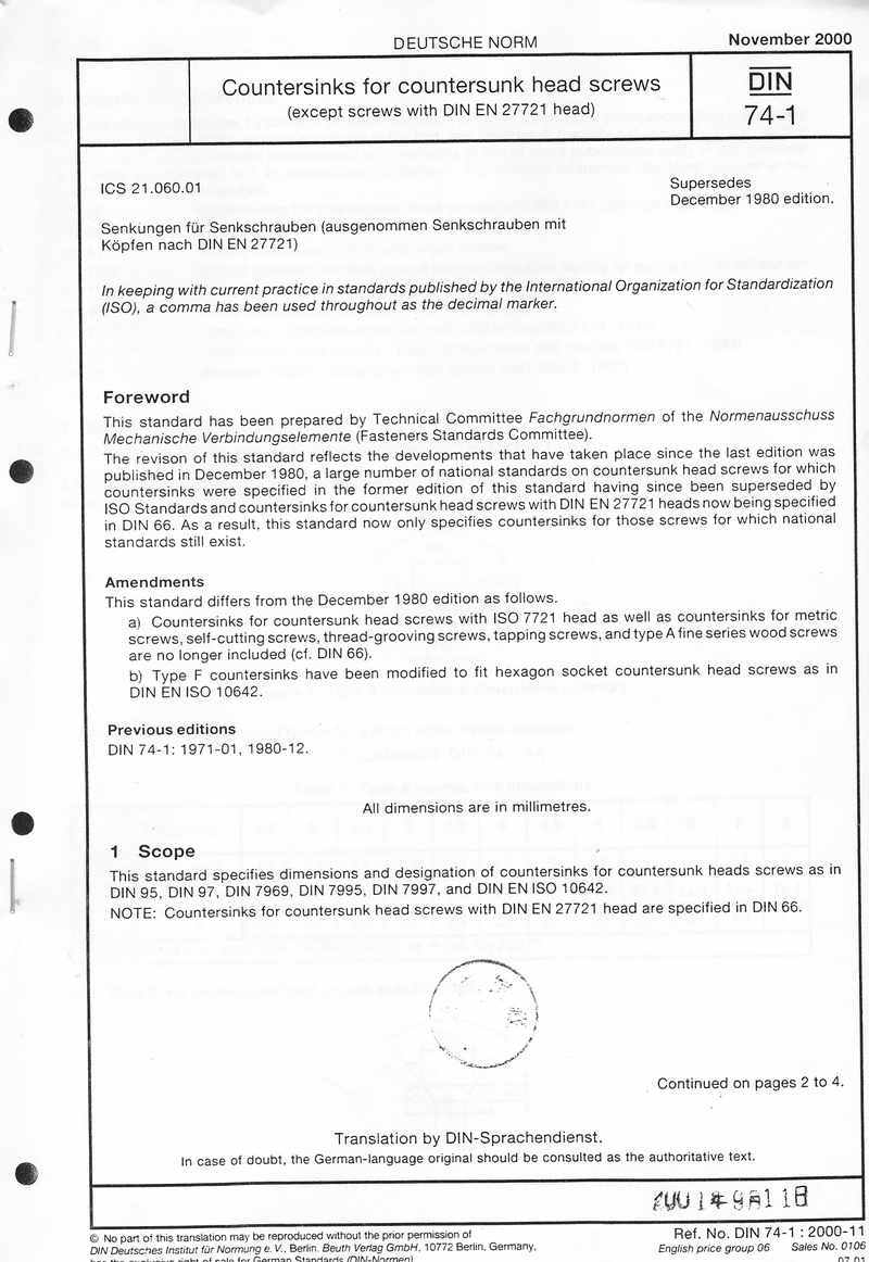
下载标准文件
din-74-1(1)
英语 · PDF · 6 页 · 12.87 MB