AS 1289.5.1.1 2003 Methods of testing soils for en
工程用途土壤试验方法 第5.1.1部分:土壤压实和密度试验——使用标准压实功确定土壤的干密度/含水率关系
AS 1289.5.1.1 2003 Methods of testing soils for engineering purposes Method 5.1.1 Soil compaction
Methods of testing soils for engineering purposes Method 5.1.1: Soil compaction and density tests—Determination of the dry density/moisture content relation of a soil using standard compactive effort
标准信息
STANDARD INFORMATION- 标准编号
- AS 1289.5.1.1 2003 Methods of testing soils for en
- 所属分类
- AS 澳大利亚标准
- 发布机构
- Standards Australia
- 版本年份
- 2000
- 文件语言
- 英语
- 文件格式
- 文件页数
- 6 页
- 文件大小
- 368.6 KB
中文名称为参考译名,文件语言以原文为准。
· 更新:
标准简介
OVERVIEW中文简介
该标准规定了使用标准压实功(596 kJ/m³)确定土壤压实后干密度与含水率关系的方法。适用于通过37.5mm筛的土壤部分,根据土壤粒径分布选择105mm或152mm直径的模具进行压实试验,以建立最大干密度及其对应的最优含水率。
English summary
This standard specifies a method for determining the relationship between moisture content and dry density of soil when compacted using standard compactive effort (596 kJ/m³). It is applicable to soil fractions passing a 37.5 mm sieve, utilizing either 105 mm or 152 mm diameter moulds depending on the particle size distribution to establish the maximum dry density and corresponding optimum moisture content.
以上为根据文件整理的内容简介。
标准内容预览
DOCUMENT PREVIEWMethods of testing soils for engineering purposes
Method 5.1.1: Soil compaction and density tests—Determination of the dry density/moisture content relation of a soil using standard compactive effort
1 SCOPE
This Standard sets out a method for the determination of the relationship between the moisture content and the dry density of a soil, when compacted, using standard compactive effort (596 kJ/m3). Compaction is conducted over a range of moisture contents to establish the maximum mass of dry soil per unit volume achievable for this compactive effort and its corresponding moisture content. The procedure is applicable to that portion of a soil that passes the 37.5 mm sieve. Soil that passes the 19.0 mm sieve is compacted in a 105 mm diameter mould. Soil that contains more than 20% of material retained on the 19.0 mm sieve is compacted in a 152 mm diameter mould.
NOTE: Corrections for oversize material are not made in this Method but may be made using Method AS 1289.5.4.1 when required for compaction control.
2 REFERENCED DOCUMENTS
The following documents are referred to in this Standard:
| AS | |
| 1152 | Specification for test sieves |
| 1289 | Methods of testing soils for engineering purposes |
| 1289.0 | Method 0: General requirements and list of methods |
| 1289.1.1 | Method 1.1: Sampling and preparation of soils—Preparation of disturbed soil samples for testing |
| 1289.2.1.1 | Method 2.1.1: Soil moisture content tests—Determination of the moisture content of a soil—Oven drying method (standard method) |
| 1289.2.1.2 | Method 2.1.2: Soil moisture content tests—Determination of the moisture content of a soil—Sand bath method (subsidiary method) |
| 1289.2.1.4 | Method 2.1.4: Soil moisture content tests—Determination of the moisture content of a soil—Microwave-oven drying method (subsidiary method) |
| 1289.2.1.5 | Method 2.1.5: Soil moisture content tests—Determination of the moisture content of a soil—Infrared lights method (subsidiary method) |
| 1289.2.1.6 | Method 2.1.6: Soil moisture content tests—Determination of the moisture content of a soil—Hotplate drying method (subsidiary method) |
| 1289.2.3.1 | Method 2.3.1: Soil moisture content tests—Establishment of correlation—Subsidiary method and the standard method |
| 1289.3.5.1 | Method 3.5.1: Soil classification tests—Determination of the soil particle density of a soil—Standard method |
| 1289.5.4.1 | Method 5.4.1: Soil compaction and density tests—Compaction control test—Dry density ratio, moisture variation and moisture ratio |
| 1289.6.1.1 | Method 6.1.1: Soil strength and consolidation tests—Determination of the California bearing ratio of a soil—Standard laboratory method for a remoulded specimen |
1
AS IS
内部资料
仅供参考
张忠辉惠存
禁止一切非法目的和活动行为,否则后果自负。
NOT FOR PUBLIC RELEASE
2
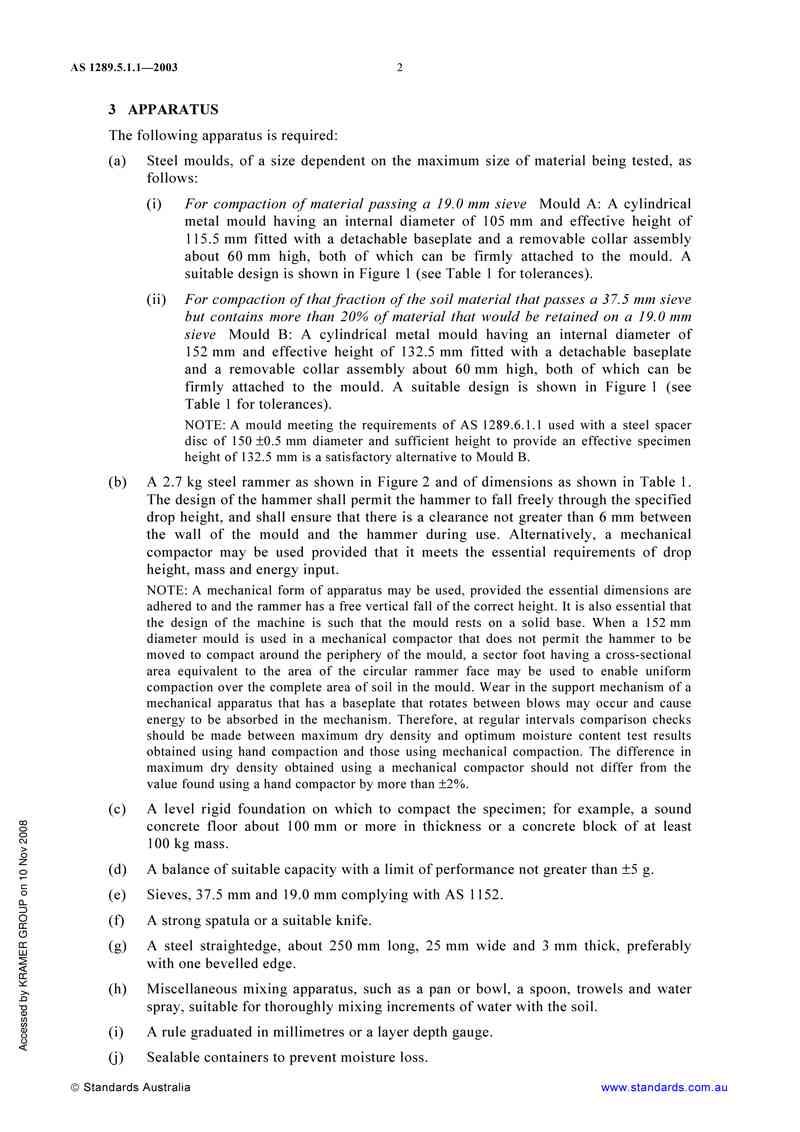
3 APPARATUS
The following apparatus is required:
(a) Steel moulds, of a size dependent on the maximum size of material being tested, as follows:
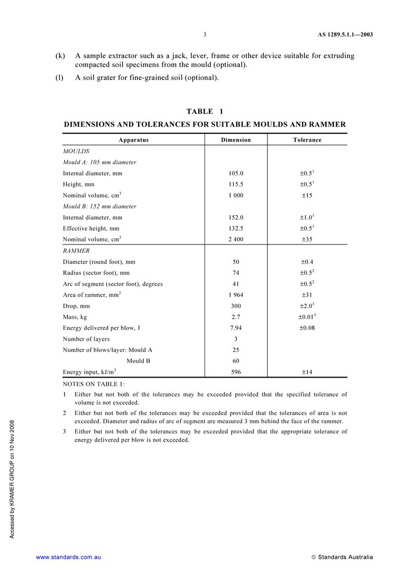
(i) For compaction of material passing a 19.0 mm sieve Mould A: A cylindrical metal mould having an internal diameter of 105 mm and effective height of 115.5 mm fitted with a detachable baseplate and a removable collar assembly about 60 mm high, both of which can be firmly attached to the mould. A suitable design is shown in Figure 1 (see Table 1 for tolerances).
(ii) For compaction of that fraction of the soil material that passes a 37.5 mm sieve but contains more than 20% of material that would be retained on a 19.0 mm sieve Mould B: A cylindrical metal mould having an internal diameter of 152 mm and effective height of 132.5 mm fitted with a detachable baseplate and a removable collar assembly about 60 mm high, both of which can be firmly attached to the mould. A suitable design is shown in Figure 1 (see Table 1 for tolerances).
NOTE: A mould meeting the requirements of AS 1289.6.1.1 used with a steel spacer disc of 150 ±0.5 mm diameter and sufficient height to provide an effective specimen height of 132.5 mm is a satisfactory alternative to Mould B.
(b) A 2.7 kg steel rammer as shown in Figure 2 and of dimensions as shown in Table 1. The design of the hammer shall permit the hammer to fall freely through the specified drop height, and shall ensure that there is a clearance not greater than 6 mm between the wall of the mould and the hammer during use. Alternatively, a mechanical compactor may be used provided that it meets the essential requirements of drop height, mass and energy input.
NOTE: A mechanical form of apparatus may be used, provided the essential dimensions are adhered to and the rammer has a free vertical fall of the correct height. It is also essential that the design of the machine is such that the mould rests on a solid base. When a 152 mm diameter mould is used in a mechanical compactor that does not permit the hammer to be moved to compact around the periphery of the mould, a sector foot having a cross-sectional area equivalent to the area of the circular rammer face may be used to enable uniform compaction over the complete area of soil in the mould. Wear in the support mechanism of a mechanical apparatus that has a baseplate that rotates between blows may occur and cause energy to be absorbed in the mechanism. Therefore, at regular intervals comparison checks should be made between maximum dry density and optimum moisture content test results obtained using hand compaction and those using mechanical compaction. The difference in maximum dry density obtained using a mechanical compactor should not differ from the value found using a hand compactor by more than ±2%.
(c) A level rigid foundation on which to compact the specimen; for example, a sound concrete floor about 100 mm or more in thickness or a concrete block of at least 100 kg mass.
(d) A balance of suitable capacity with a limit of performance not greater than ±5 g.
(e) Sieves, 37.5 mm and 19.0 mm complying with AS 1152.
(f) A strong spatula or a suitable knife.
(g) A steel straightedge, about 250 mm long, 25 mm wide and 3 mm thick, preferably with one bevelled edge.
(h) Miscellaneous mixing apparatus, such as a pan or bowl, a spoon, trowels and water spray, suitable for thoroughly mixing increments of water with the soil.
(i) A rule graduated in millimetres or a layer depth gauge.
(j) Sealable containers to prevent moisture loss.
3
TABLE 1 DIMENSIONS AND TOLERANCES FOR SUITABLE MOULDS AND RAMMER
(k) A sample extractor such as a jack, lever, frame or other device suitable for extruding compacted soil specimens from the mould (optional).
(l) A soil grater for fine-grained soil (optional).
| Apparatus | Dimension | Tolerance |
|---|---|---|
| MOULDS | ||
| Mould A: 105 mm diameter | ||
| Internal diameter, mm | 105.0 | ±0.51 |
| Height, mm | 115.5 | ±0.51 |
| Nominal volume, cm3 | 1 000 | ±15 |
| Mould B: 152 mm diameter | ||
| Internal diameter, mm | 152.0 | ±1.01 |
| Effective height, mm | 132.5 | ±0.51 |
| Nominal volume, cm3 | 2 400 | ±35 |
| RAMMER | ||
| Diameter (round foot), mm | 50 | ±0.4 |
| Radius (sector foot), mm | 74 | ±0.52 |
| Arc of segment (sector foot), degrees | 41 | ±0.52 |
| Area of rammer, mm2 | 1 964 | ±31 |
| Drop, mm | 300 | ±2.03 |
| Mass, kg | 2.7 | ±0.013 |
| Energy delivered per blow, J | 7.94 | ±0.08 |
| Number of layers | 3 | |
| Number of blows/layer: Mould A | 25 | |
| Mould B | 60 | |
| Energy input, kJ/m3 | 596 | ±14 |
NOTES ON TABLE 1:
- Either but not both of the tolerances may be exceeded provided that the specified tolerance of volume is not exceeded.
- Either but not both of the tolerances may be exceeded provided that the tolerances of area is not exceeded. Diameter and radius of arc of segment are measured 3 mm behind the face of the rammer.
- Either but not both of the tolerances may be exceeded provided that the appropriate tolerance of energy delivered per blow is not exceeded.
4
Smooth finish on bore
Push fit
NOTE: This design has been found satisfactory, but alternative designs may be employed provided that the essential dimensions in Table 1 are met.
FIGURE 1 DETAILS OF TYPICAL TYPE A AND TYPE B MOULDS
5
4 PROCEDURE
PARTS LIST AND TYPICAL DIMENSIONS
| 1 | Handle | Ø 30 × 3 thick, black low-carbon steel tube 90 long |
| 2 | Rod | Ø 19 bright low-carbon steel rod |
| 3 | Guide washer | 5 low-carbon steel flat Ø 40 |
| 4 | Tube | Ø 26 × 3.2 thick, black low-carbon steel tube 90 long |
| 5 | Frame washer | 5 low-carbon steel flat Ø 75 |
| 6 | Guides | Ø 8 low-carbon steel rods—3 no. |
| 7 | Full ring | 25 × 3 low-carbon steel flat |
| 8 | Washer pad | Ø 45 leather |
| 9 | Rammer | Ø 50 bright low-carbon steel bar |
| 10 | Part ring | 25 × 3 low-carbon steel flat |
NOTE: This design has been found satisfactory, but alternative designs and materials may be employed provided that the essential requirements in Table 1 are met.
DIMENSIONS IN MILLIMETRES
FIGURE 2 2.7 kg RAMMER
The procedure shall be as follows:
(a) Prepare the sample in accordance with AS 1289.1.1.
(b) Screen the prepared sample over a 19.0 mm sieve. If necessary, brush fine material from the material retained on the 19.0 mm sieve. Determine the mass of the retained 19.0 mm material and calculate the percentage retained on the 19.0 mm sieve from the following equation:
Po = 100mo / m ... (4)
where
Po = percentage by mass of + 19.0 mm (oversize) material
mo = wet mass of + 19.0 mm (oversize) material, in grams
m = wet mass of the total sample, before screening, in grams
6
预览内容由文件识别整理,表格、公式及文字请以原始文件为准。
原文图片预览
PAGE IMAGES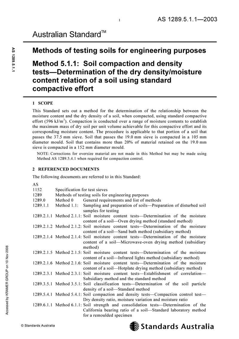
下载标准文件
AS 1289.5.1.1 2003 Methods of testing soils for en
英语 · PDF · 6 页 · 368.6 KB