NF A85-004-中文
电弧焊接用设备和相关技术 - 用在仪器上的信号灯和图形符号
NF A85-004-中文
Equipment and related techniques for arc welding - Signal lights and graphic symbols used on instruments
标准信息
STANDARD INFORMATION- 标准编号
- NF A85-004-中文
- 所属分类
- NF 法国标准
- 发布机构
- AFNOR
- 版本年份
- 1988
- 文件语言
- 英语
- 文件格式
- 文件页数
- 6 页
- 文件大小
- 377.1 KB
中文名称为参考译名,文件语言以原文为准。
· 更新:
标准简介
OVERVIEW中文简介
本标准规定了用于电弧焊接设备及相关技术仪器上的图形符号和信号灯的定义、形状、比例及含义。它旨在用简明易懂的图形符号代替文字说明,以识别设备罩壳和配电箱上的不同工作机构和控制机构功能。该标准适用于所有电弧焊接设备及相关技术领域。
English summary
This standard defines the shapes, relative proportions, and meanings of graphic symbols and signal lights used on instruments for arc welding equipment and related techniques. It aims to replace textual descriptions with clear graphic symbols to identify the functions of operating and control mechanisms on equipment housings and distribution boards. The standard applies to all arc welding equipment and related technical fields.
以上为根据文件整理的内容简介。
相关标签
标准内容预览
DOCUMENT PREVIEW3. 图形符号的使用
3.1 图形符号的位置
为了使图形符号不干扰已识别设备机构的确认,最好把图形符号放于机构下方,或者紧挨着机构左边放置,或者放置机构中间的偏下方。
如果涉及到 2 个位置的转换器,比如接通或断开一功能回路,应该在转换器两个位置尽端附近对应每个位置放置一个代表其功能的图形符号。
3.2 复杂功能循环焊接设备
复杂功能循环焊接设备中,仅仅使用图形符号即不充分或者也很难解释。
这种情况,制造商会在设备循环功能控制罩壳上分别表示出不同循环阶段对应的调节机构和控制结构,用数字表明不同循环阶段(例如 图 1)。
3.3 有自定义的符号
这些符号用来识别一项功能的调节机构或者控制机构,或者指明所识别机构对应的是哪个功能或哪个回路。它们也可以确定一机构的位置。
这样,比如,符号 61(保险丝),单独使用,对机器保险丝盒进行定位(用回路符号来辨别每个保险丝);当被放在灯筒旁边时,它可以表示信号灯(可熔保险丝)(用相应的回路符号来识别每个信号灯)。
3.4 图形符号的组合
需要明确指出组合了 2 个或者很多个符号的图形符号的含义。
示例:符号 59(接入)和符号 53(水冷却)组合代表的是被识别机构是冷却水回路的入口或者冷却水到达回路的一个部件。
图 2 接入冷却水的示例
6
Révision de la présente publication
Le contenu technique des publications de la CEI est constamment revu par la Commission afin d'assurer qu'il reflète bien l'état actuel de la technique.
Les renseignements relatifs à ce travail de révision, à l'établissement des éditions révisées et aux mises à jour peuvent être obtenus auprès des Comités nationaux de la CEI et en consultant les documents ci-dessous :
- Bulletin de la CEI
- Annuaire de la CEI
- Catalogue des publications de la CEI
Publié annuellement
Terminologie
En ce qui concerne la terminologie générale, le lecteur se reportera à la Publication 50 de la CEI : Vocabulaire Electrotechnique International (VEI), qui est établie sous forme de chapitres séparés traitant chacun d'un sujet défini, l'Index général étant publié séparément. Des détails complets sur le VEI peuvent être obtenus sur demande.
Les termes et définitions figurant dans la présente publication ont été soit repris du VEI, soit spécifiquement approuvés aux fins de cette publication.
Symboles graphiques et littéraux
Pour les symboles graphiques, symboles littéraux et signes d'usage général approuvés par la CEI, le lecteur consultera :
- la Publication 27 de la CEI : Symboles littéraux à utiliser en électrotechnique ;
- la Publication 617 de la CEI : Symboles graphiques pour schémas.
Les symboles et signes contenus dans la présente publication ont été soit repris des Publications 27 ou 617 de la CEI, soit spécifiquement approuvés aux fins de cette publication.
Publications de la CEI établies par le même Comité d'Etudes
L'attention du lecteur est attirée sur la page 3 de la couverture, qui énumère les publications de la CEI préparées par le Comité d'Etudes qui a établi la présente publication.
Revision of this publication
The technical content of IEC publications is kept under constant review by the IEC, thus ensuring that the content reflects current technology.
Information on the work of revision, the issue of revised editions and amendment sheets may be obtained from IEC National Committees and from the following IEC sources :
- IEC Bulletin
- IEC Yearbook
- Catalogue of IEC Publications
Published yearly
Terminology
For general terminology, readers are referred to IEC Publication 50 : International Electrotechnical Vocabulary (IEV), which is issued in the form of separate chapters each dealing with a specific field, the General Index being published as a separate booklet. Full details of the IEV will be supplied on request.
The terms and definitions contained in the present publication have either been taken from the IEV or have been specifically approved for the purpose of this publication.
Graphical and letter symbols
For graphical symbols, and letter symbols and signs approved by the IEC for general use, readers are referred to :
- IEC Publication 27 : Letter symbols to be used in electrical technology ;
- IEC Publication 617 : Graphical symbols for diagrams.
The symbols and signs contained in the present publication have either been taken from IEC Publications 27 or 617, or have been specifically approved for the purpose of this publication.
IEC publications prepared by the same Technical Committee
The attention of readers is drawn to the inside of the back cover, which lists IEC publications issued by the Technical Committee which has prepared the present publication.
2
SOMMAIRE
| pages | |
|---|---|
| Extrait de l'arrêté du 12 février 2004 relatif à la composition du cahier des clauses techniques générales applicables aux marchés publics de travaux et approuvant ou modifiant divers fascicules | III |
| Circulaire n° 2004-16 du 4 mars 2004 relative à la modification du fascicule 56 du Cahier des clauses techniques générales applicables aux marchés publics de travaux | V |
| Rapport de présentation | IX |
| Fascicule 56 | |
| Table des matières | 1 |
| Fascicule 56 | 7 |
| Annexes | 77 |
| Liste des membres du groupe de travail | 129 |
TABLE DES MATIÈRES
| Pages | |
| Extraits du décret n° 83-253 du 8 avril 1987 relatif à la composition du cahier des clauses techniques générales applicables aux marchés publics de travaux et approuvant ou modifiant divers fascicules | V |
| Fascicule n° 76 — Textes et commentaires | 2 |
| Annexes | 41 |
| Rapport de présentation | 71 |
:current
Foreword
This document (EN 10216-3:2002) has been prepared by Technical Committee EC/TC 29, "Steel tubes and fittings for steel tubes", the secretariat of which is held by UNI.
This European Standard shall be given the status of a national standard, either by publication of an identical text or by endorsement, at the latest by November 2002, and conflicting national standards shall be withdrawn at the latest by November 2002.
This document has been prepared under a mandate given to CEN by the European Commission and the European Free Trade Association, and supports essential requirements of EU Directive(s).
For relationship with EU Directive(s), see informative annex ZA, which is an integral part of this document.
Other Parts of EN 10216 are:
| Part 1: | Non-alloy steel tubes with specified room temperature properties |
| Part 2: | Non-alloy and alloy steel tubes with specified elevated temperature properties |
| Part 4: | Non-alloy and alloy steel tubes with specified low temperature properties |
| Part 5: | Stainless steel tubes |
Another European Standard series covering tubes for pressure purposes is:
| EN 10217: | Welded steel tubes for pressure purposes |
According to the CEN/CENELEC Internal Regulations, the national standards organizations of the following countries are bound to implement this European Standard: Austria, Belgium, Czech Republic, Denmark, Finland, France, Germany, Greece, Iceland, Ireland, Italy, Luxembourg, Malta, Netherlands, Norway, Portugal, Spain, Sweden, Switzerland and the United Kingdom.
5
ISO 657-1 : 1988 (E)
Table 1 — Dimensions and sectional properties of hot-rolled equal-leg angles (concluded)
| Designation | Mass kg/m | Sectional area cm² | Dimensions | Distances of centre of gravity | Sectional properties about axes | |||||||||||
|---|---|---|---|---|---|---|---|---|---|---|---|---|---|---|---|---|
| X-X = Y-Y | U-U | V-V | ||||||||||||||
| A mm | l mm | rroot mm | cx = cy cm | cu cm | cv cm | Ix = Iy cm⁴ | rx = ry cm | Zx = Zy cm³ | Iu cm⁴ | ru cm | Iv cm⁴ | rv cm | Zv cm³ | |||
| (1) | (2) | (3) | (4) | (5) | (6) | (7) | (8) | (9) | (10) | (11) | (12) | (13) | (14) | (15) | (16) | (17) |
| 200 × 200 × 16 | 48,5 | 61,8 | 200 | 16 | 18 | 5,52 | 14,1 | 7,81 | 2 340 | 6,16 | 162 | 3 720 | 7,76 | 960 | 3,94 | 123 |
| 200 × 200 × 20 | 59,9 | 76,3 | 200 | 20 | 18 | 5,68 | 14,1 | 8,04 | 2 850 | 6,11 | 199 | 4 530 | 7,70 | 1 170 | 3,92 | 146 |
| 200 × 200 × 24 | 71,1 | 90,6 | 200 | 24 | 18 | 5,84 | 14,1 | 8,26 | 3 330 | 6,06 | 235 | 5 280 | 7,64 | 1 380 | 3,90 | 167 |
| 250 × 250 × 28 | 104 | 133 | 250 | 28 | 18 | 7,24 | 17,7 | 10,2 | 7 700 | 7,62 | 433 | 12 200 | 9,61 | 3 170 | 4,89 | 309 |
| 250 × 250 × 35 | 128 | 163 | 250 | 35 | 18 | 7,50 | 17,7 | 10,6 | 9 260 | 7,54 | 529 | 14 700 | 9,48 | 3 860 | 4,87 | 364 |
NOTES
- Member countries may choose, to be included in their national standards, the sizes which are required to meet their demand.
- For the angles so chosen, only thicknesses which can be rolled in their mills to meet the demand of the users may be selected from the list of thicknesses corresponding to equal angles in table 1.
- The sectional area has been calculated using the formula
S = [l/2 A - l) + 0,214 6 (rroot² - 2rtoe²)] × 1/100
where
S is the sectional area, in square centimetres;
l is the thickness, in millimetres;
rroot is the root radius, in millimetres;
rtoe is the toe radius, in millimetres;
A is the leg length, in millimetres.
- Mass is calculated on the basis of density of steel of 7,85 kg/dm³.
4
预览内容由文件识别整理,表格、公式及文字请以原始文件为准。
原文图片预览
PAGE IMAGES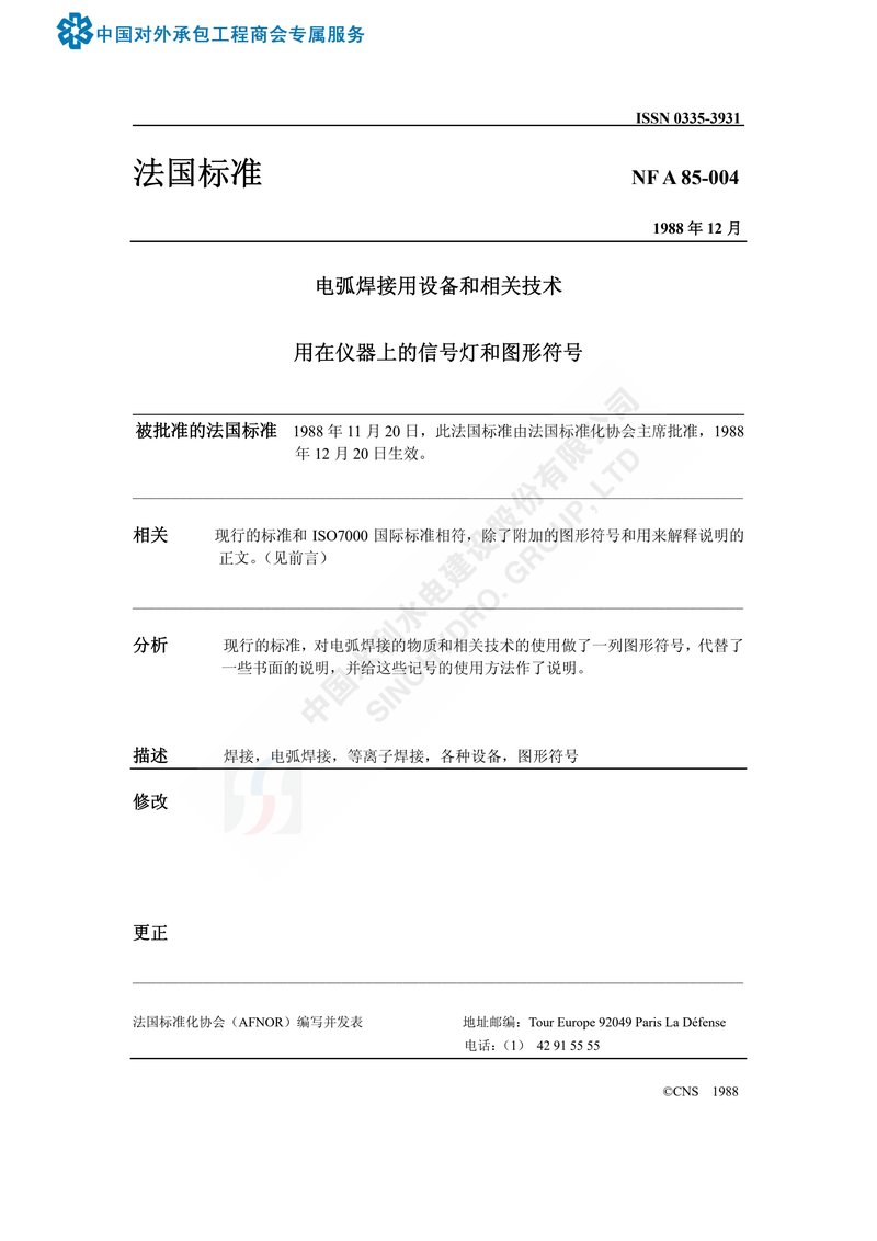
下载标准文件
NF A85-004-中文
英语 · PDF · 6 页 · 377.1 KB