IEC 60826-03
架空输电线路设计准则
IEC 60826-03
Design criteria of overhead transmission lines
标准信息
STANDARD INFORMATION- 标准编号
- IEC 60826-03
- 所属分类
- IEC 国际电工标准
- 发布机构
- IEC
- 版本年份
- 2003
- 文件语言
- 英语
- 文件格式
- 文件页数
- 6 页
- 文件大小
- 17.85 MB
中文名称为参考译名,文件语言以原文为准。
· 更新:
标准简介
OVERVIEW中文简介
该标准规定了架空输电线路的设计准则,包括气候载荷(风、冰)、组件强度及极限状态的计算方法。它适用于输电线路系统的设计,旨在确保线路在特定气象条件下的安全性和可靠性。
English summary
This standard specifies the design criteria for overhead transmission lines, covering climatic loads (wind, ice), component strength, and limit states. It applies to the design of transmission line systems to ensure safety and reliability under specific meteorological conditions.
以上为根据文件整理的内容简介。
相关标签
标准内容预览
DOCUMENT PREVIEWFigures and Tables
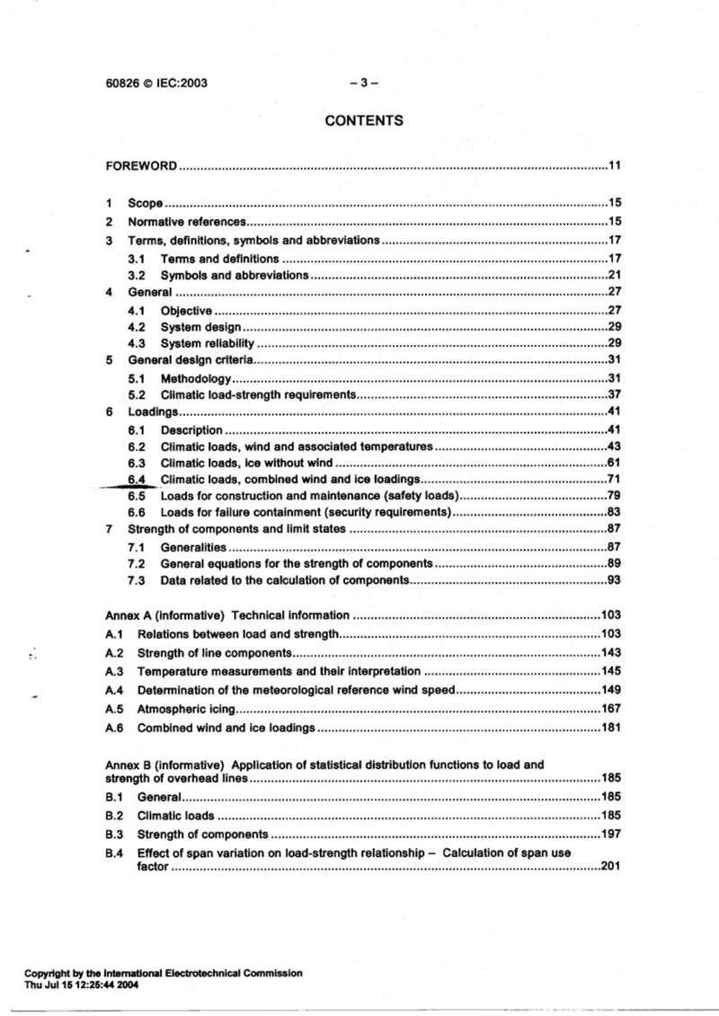
Figure A.9 – Type of accreted in-cloud icing as a function of wind speed and temperature................................................................................................................173
Figure A.10 – Strategy flow chart for utilizing meteorological data, icing models and field measurements of ice loads................................................................................................................177
Figure B.1 – Fitting of Gumbel distribution with wind data histogram................................................................................................................187
Figure B.2 – Fitting of Gumbel distribution with yearly minimum temperature histogram................................................................................................................193
Figure B.3 – Fitting of Gamma distribution with ice load histogram................................................................................................................195
Figure B.4 – Fitting data from in-cloud icing with Gumbel distribution................................................................................................................197
Figure B.5 – Fitting of Weibull distribution with strength data of lattice supports................................................................................................................199
Figure C.1 – Probability density function of standardized normal distribution................................................................................................................219
Figure C.2 – Probability density function of standardized log-normal distribution................................................................................................................223
Figure C.3 – Probability density function of standardized Gumbel distribution................................................................................................................227
Figure C.4 – Probability density function of standardized Weibull distribution for parameter p3 = 0,5; 1,0 and 2,0................................................................................................................231
Figure C.5 – Probability density function of standardized Gamma distribution for parameter p3 = 0,5; 1,0 and 2,0................................................................................................................235
Figure C.6 – Probability density function of standardized beta distribution for parameters r = 5,0, t = 5,5; 6,0 and 7,0................................................................................................................239
Table 1 – Reliability levels for transmission lines................................................................................................................35
Table 2 – Default γf factors for adjustment of climatic loads in relation to return period T vs. 50 years................................................................................................................39
Table 3 – Design requirements for the system................................................................................................................39
Table 4 – Classification of terrain categories................................................................................................................45
Table 5 – Correction factor τ of dynamic reference wind pressure q0 due to altitude and temperatures................................................................................................................47
Table 6 – Non-uniform ice loading conditions................................................................................................................71
Table 7 – Return period of combined ice and wind load................................................................................................................73
Table 8 – Drag coefficients of ice-covered conductors................................................................................................................77
Table 9 – Additional security measures................................................................................................................87
Table 10 – Number of supports subjected to maximum load intensity during any single occurrence of a climatic event................................................................................................................89
Table 11 – Strength factor φN related to the number N of components or elements subjected to the critical load intensity................................................................................................................91
Table 12 – Values of φS2................................................................................................................91
Table 13 – Typical strength coordination of line components................................................................................................................93
Table 14 – Damage and failure limits of supports................................................................................................................93
Table 15 – Damage and failure limits of foundations................................................................................................................95
Table 16 – Damage and failure limits of conductors and ground wires................................................................................................................95
Table 17 – Damage and failure limit of interface components................................................................................................................97
6
Révision de la présente publication
Le contenu technique des publications de la CEI est constamment revu par la Commission afin d'assurer qu'il reflète bien l'état actuel de la technique.
Les renseignements relatifs à ce travail de révision, à l'établissement des éditions révisées et aux mises à jour peuvent être obtenus auprès des Comités nationaux de la CEI et en consultant les documents ci-dessous :
- Bulletin de la CEI
- Annuaire de la CEI
- Catalogue des publications de la CEI
Publié annuellement
Terminologie
En ce qui concerne la terminologie générale, le lecteur se reportera à la Publication 50 de la CEI : Vocabulaire Electrotechnique International (VEI), qui est établie sous forme de chapitres séparés traitant chacun d'un sujet défini, l'Index général étant publié séparément. Des détails complets sur le VEI peuvent être obtenus sur demande.
Les termes et définitions figurant dans la présente publication ont été soit repris du VEI, soit spécifiquement approuvés aux fins de cette publication.
Symboles graphiques et littéraux
Pour les symboles graphiques, symboles littéraux et signes d'usage général approuvés par la CEI, le lecteur consultera :
- la Publication 27 de la CEI : Symboles littéraux à utiliser en électrotechnique ;
- la Publication 617 de la CEI : Symboles graphiques pour schémas.
Les symboles et signes contenus dans la présente publication ont été soit repris des Publications 27 ou 617 de la CEI, soit spécifiquement approuvés aux fins de cette publication.
Publications de la CEI établies par le même Comité d'Etudes
L'attention du lecteur est attirée sur la page 3 de la couverture, qui énumère les publications de la CEI préparées par le Comité d'Etudes qui a établi la présente publication.
Revision of this publication
The technical content of IEC publications is kept under constant review by the IEC, thus ensuring that the content reflects current technology.
Information on the work of revision, the issue of revised editions and amendment sheets may be obtained from IEC National Committees and from the following IEC sources :
- IEC Bulletin
- IEC Yearbook
- Catalogue of IEC Publications
Published yearly
Terminology
For general terminology, readers are referred to IEC Publication 50 : International Electrotechnical Vocabulary (IEV), which is issued in the form of separate chapters each dealing with a specific field, the General Index being published as a separate booklet. Full details of the IEV will be supplied on request.
The terms and definitions contained in the present publication have either been taken from the IEV or have been specifically approved for the purpose of this publication.
Graphical and letter symbols
For graphical symbols, and letter symbols and signs approved by the IEC for general use, readers are referred to :
- IEC Publication 27 : Letter symbols to be used in electrical technology ;
- IEC Publication 617 : Graphical symbols for diagrams.
The symbols and signs contained in the present publication have either been taken from IEC Publications 27 or 617, or have been specifically approved for the purpose of this publication.
IEC publications prepared by the same Technical Committee
The attention of readers is drawn to the inside of the back cover, which lists IEC publications issued by the Technical Committee which has prepared the present publication.
2
NORME INTERNATIONALE INTERNATIONAL STANDARD МЕЖДУНАРОДНЫЙ СТАНДАРТ
|
NORME INTERNATIONALE INTERNATIONAL STANDARD МЕЖДУНАРОДНЫЙ СТАНДАРТ |
CEI IEC 50(426) Première édition First edition 1990-10 Vocabulaire Electrotechnique InternationalChapitre 426 : Matériel électrique pour atmosphères explosives International Electrotechnical VocabularyChapter 426 : Electrical apparatus for explosive atmospheres Международный Электротехнический СловарьГлава 426 : Электрооборудование для взрывоопасных сред © CEI 1990 Droits de reproduction réservés - Copyright - all rights reserved - Право издания охраняется законом Aucune partie de cette publication ne peut être reproduite ni utilisée sous quelque forme que ce soit et par aucun procédé, électronique ou mécanique, y compris la photocopie et les microfilms, sans l'accord écrit de l'éditeur. No part of this publication may be reproduced or utilized in any form or by any means, electronic or mechanical, including photocopying and microfilm, without permission in writing from the publisher. Запрещается Без письменного разрешения издателя воспроизведение или копирование этой публикации или ее части в любой форме или любыми средствами — электронными или механическими, включая фотоконю и микрофильм. Bureau central de la Commission Electrotechnique Internationale 3, rue de Varembé Genève Suisse
|
50(715) © IEC:1996
CONTENTS
| FOREWORD | VII | |
| PREFACE | VII | |
| Sections | ||
| 715-01 | Basic terms | 1 |
| 715-02 | Resources | 10 |
| 715-03 | Calls | 17 |
| 715-04 | Times and delays | 22 |
| 715-05 | Traffic | 24 |
| 715-06 | Circuit groups | 32 |
| 715-07 | Traffic engineering | 34 |
| 715-08 | Networks | 41 |
| 715-09 | Circuit switched networks | 46 |
| 715-10 | Message switched networks | 51 |
| 715-11 | Packet switched networks | 52 |
| Index | 53 |
:current
Foreword
This document (EN 10216-3:2002) has been prepared by Technical Committee EC/TC 29, "Steel tubes and fittings for steel tubes", the secretariat of which is held by UNI.
This European Standard shall be given the status of a national standard, either by publication of an identical text or by endorsement, at the latest by November 2002, and conflicting national standards shall be withdrawn at the latest by November 2002.
This document has been prepared under a mandate given to CEN by the European Commission and the European Free Trade Association, and supports essential requirements of EU Directive(s).
For relationship with EU Directive(s), see informative annex ZA, which is an integral part of this document.
Other Parts of EN 10216 are:
| Part 1: | Non-alloy steel tubes with specified room temperature properties |
| Part 2: | Non-alloy and alloy steel tubes with specified elevated temperature properties |
| Part 4: | Non-alloy and alloy steel tubes with specified low temperature properties |
| Part 5: | Stainless steel tubes |
Another European Standard series covering tubes for pressure purposes is:
| EN 10217: | Welded steel tubes for pressure purposes |
According to the CEN/CENELEC Internal Regulations, the national standards organizations of the following countries are bound to implement this European Standard: Austria, Belgium, Czech Republic, Denmark, Finland, France, Germany, Greece, Iceland, Ireland, Italy, Luxembourg, Malta, Netherlands, Norway, Portugal, Spain, Sweden, Switzerland and the United Kingdom.
5
1 Scope
This Part of EN 10216 specifies the technical delivery conditions in two test categories for seamless tubes of circular cross section, made of weldable alloyed fine grained steel.
2 Normative references
This European Standard incorporates by date or undated reference, provisions from other publications. These normative references are cited at the appropriate places in the text and the publications are listed hereafter. For date references, subsequent amendments to or revisions of, any of these publications apply to this European Standard only when incorporated in it by amendment or revision. For undated references the latest edition of the publication referred to applies (including amendments).
The requirements of this European Standard rule when they differ from those in the standards and documents referred to below:
EN 10002-1, Metallic materials - Tensile testing - Part 1: Method of test (at ambient temperature).
EN 10002-5, Metallic materials - Tensile testing - Part 5: Method of testing (at elevated temperature).
EN 10020, Definitions and classification of grades of steel.
EN 10021, General technical delivery requirements for steel and iron products.
EN 10045-1, Metallic materials - Charpy impact test - Part 1: Test method.
EN 10052, Vocabulary of heat treatment terms for ferrous products.
EN 10204, Metallic products - Types of inspection documents.
EN 10027-1, Designation systems for steels - Part 1: Steel names, principle symbols.
EN 10027-2, Designation systems for steels Part 2: Numerical systems.
ENV 10220, Seamless and welded steel tubes - Dimensions and masses per unit length
EN 10233, Metallic materials - Tubes - Flattening test.
EN 10234, Metallic materials - Tubes - Drift expanding test.
EN 10236, Metallic materials - Tubes - Ring expanding test.
EN 10237, Metallic materials - Tubes - Ring tensile test.
EN 10246-1, Non-Destructive Testing of steel tubes Part 1: Automatic electromagnetic testing of seamless and welded (except submerged arc welded) ferromagnetic steel tubes for verification of hydraulic leak-tightness.
EN 10246-5, Non-Destructive Testing of steel tubes - Part 5: Automatic full peripheral magnetic transducer/flux leakage testing of seamless and welded (except submerged arc-welded) ferromagnetic steel tubes for the detection of longitudinal imperfections.
EN 10246-6, Non-Destructive Testing of steel tubes - Part 6: Automatic full peripheral ultrasonic testing of seamless steel tubes for the detection of transverse imperfections.
EN 10246-7, Non-Destructive Testing of steel tubes - Part 7: Automatic full peripheral ultrasonic testing of seamless and welded (except submerged arc welded) steel tubes for the detection of longitudinal imperfections.
6
预览内容由文件识别整理,表格、公式及文字请以原始文件为准。
原文图片预览
PAGE IMAGES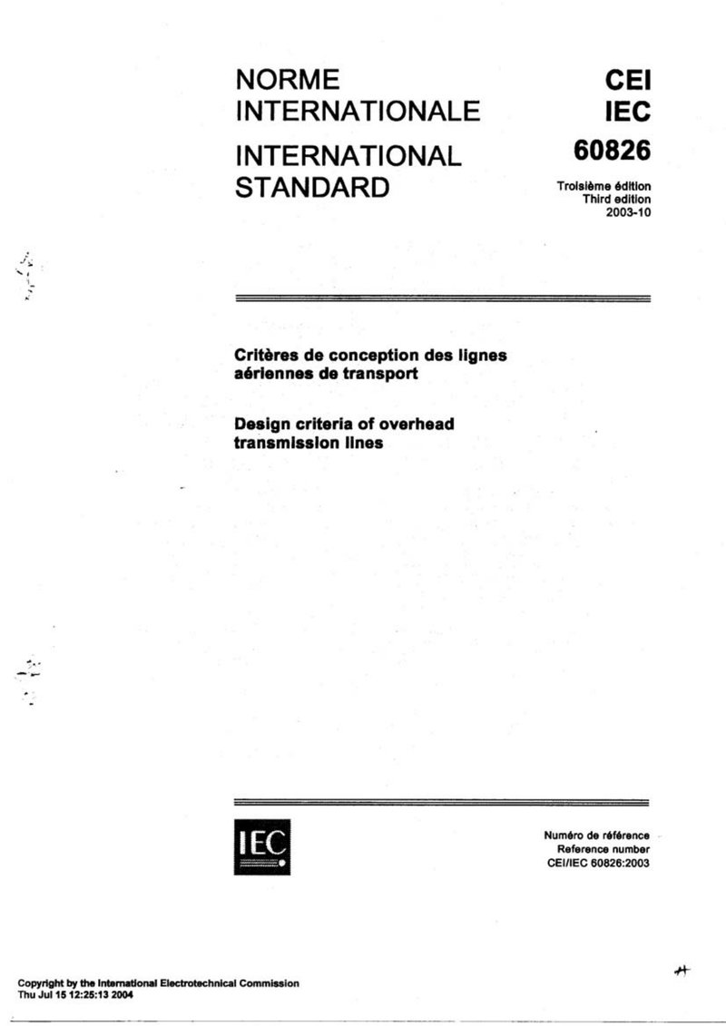
下载标准文件
IEC 60826-03
英语 · PDF · 6 页 · 17.85 MB