标准信息
STANDARD INFORMATION- 标准编号
- DIN 2638
- 所属分类
- DIN 德国标准
- 发布机构
- DIN
- 版本年份
- 1964
- 文件语言
- 英语
- 文件格式
- 文件页数
- 6 页
- 文件大小
- 868.04 KB
中文名称为参考译名,文件语言以原文为准。
· 更新:
标准简介
OVERVIEW中文简介
该标准规定了公称压力为160 bar的焊接颈法兰(Vorschweißflansche)的尺寸、几何形状及材料要求。主要涵盖法兰的公称直径、壁厚、螺栓孔分布及重量等详细技术参数,适用于C22碳钢材料,并规定了最高使用温度限制。
English summary
This standard specifies the dimensions, geometry, and material requirements for welding neck flanges with a nominal pressure of 160 bar. It covers detailed technical parameters such as nominal diameter, wall thickness, bolt hole distribution, and weight, specifically for C22 carbon steel material, including maximum operating temperature limits.
以上为根据文件整理的内容简介。
相关标签
标准内容预览
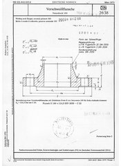
DOCUMENT PREVIEWVorschweißflansche
Nenndruck 160
Welding neck flanges; nominal pressure 160
Brides à souder à collerette; pression nominale 160
Maße in mm
z/ = √(Rz = 160)
y/ = √(Rz = 40) gedreht
x/ = √(Rz = 16)
Form der Schweißfuge:
Regelausführung
s ≤ 16 Fugenform 22 DIN 2559
s > 16 Fugenform 3 DIN 2559
Sonderausführung
siehe DIN 2559
Bezeichnung eines Vorschweißflansches mit Dichtleiste Form E von Nennweite 100 für Rohr-Außendurchmesser d1 - 114,3 mm aus C 22:
Flansch E 100 x 114,3 DIN 2638 - C 22
Fortsetzung Seite 2
Fachnormenausschuß Rohre, Rohrverbindungen und Rohrleitungen (FR) im Deutschen Normenausschuß (DNA)
1
DIN 2638
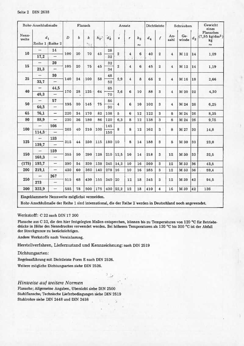
| Nennweite | Rohr-Anschlußmaße | Flansch | Ansatz | Dichtleiste | Schrauben | Gewicht eines Flansches (7,85 kg/dm³) kg ≈ | ||||||||||
|---|---|---|---|---|---|---|---|---|---|---|---|---|---|---|---|---|
| d₁ Reihe 1 | Reihe 2 | D | b | k | h₁ | d₃ | s | r | h₂ ≈ | d₄ | f | Anzahl | Gewinde | d₂ | ||
| 10 | — | 14 | 100 | 20 | 70 | 45 | 28 | 2 | 4 | 6 | 40 | 2 | 4 | M 12 | 14 | 1,09 |
| 17,2 | — | 32 | ||||||||||||||
| 15 | — | 20 | 105 | 20 | 75 | 45 | 32 | 2 | 4 | 6 | 45 | 2 | 4 | M 12 | 14 | 1,19 |
| 21,3 | — | 34 | ||||||||||||||
| 25 | — | 30 | 140 | 24 | 100 | 58 | 48 | 2,9 | 4 | 8 | 68 | 2 | 4 | M 16 | 18 | 2,66 |
| 33,7 | — | 52 | ||||||||||||||
| 40 | — | 44,5 | 170 | 28 | 125 | 64 | 65 | 3,6 | 6 | 10 | 88 | 3 | 4 | M 20 | 22 | 4,30 |
| 48,3 | — | 70 | ||||||||||||||
| 50 | — | 57 | 195 | 30 | 145 | 75 | 86 | 4 | 6 | 10 | 102 | 3 | 4 | M 24 | 26 | 6,25 |
| 60,3 | — | 90 | ||||||||||||||
| 65 | 76,1 | — | 220 | 34 | 170 | 82 | 108 | 5 | 6 | 12 | 122 | 3 | 8 | M 24 | 26 | 8,35 |
| 80 | 88,9 | — | 230 | 36 | 180 | 86 | 120 | 6,3 | 8 | 12 | 138 | 3 | 8 | M 24 | 26 | 9,75 |
| 100 | — | 108 | 265 | 40 | 210 | 100 | 145 | 8 | 8 | 12 | 162 | 3 | 8 | M 27 | 30 | 14,8 |
| 114,3 | — | 150 | ||||||||||||||
| 125 | — | 133 | 315 | 44 | 250 | 115 | 180 | 10 | 8 | 14 | 188 | 3 | 8 | M 30 | 33 | 23,0 |
| 139,7 | — | |||||||||||||||
| 150 | — | 159 | 355 | 50 | 290 | 128 | 210 | 12,5 | 10 | 14 | 218 | 3 | 12 | M 30 | 33 | 32,5 |
| 168,3 | — | |||||||||||||||
| (175) | 193,7 | — | 390 | 54 | 320 | 138 | 245 | 14,2 | 10 | 16 | 260 | 3 | 12 | M 33 | 36 | 43,5 |
| 200 | 219,1 | — | 430 | 60 | 360 | 140 | 278 | 16 | 10 | 16 | 285 | 3 | 12 | M 33 | 36 | 59,4 |
| 250 | — | 267 | 515 | 68 | 430 | 155 | 340 | 20 | 12 | 18 | 345 | 3 | 12 | M 39 | 42 | 94,5 |
| 273 | — | |||||||||||||||
| 300 | 323,9 | — | 585 | 78 | 500 | 175 | 400 | 22,2 | 12 | 18 | 410 | 4 | 16 | M 39 | 42 | 136 |
| Eingeklammerte Nennweite möglichst vermeiden. | ||||||||||||||||
| Rohr-Anschlußmaße der Reihe 1 sind international, die der Reihe 2 werden in Deutschland noch angewendet. | ||||||||||||||||
Werkstoff: C 22 nach DIN 17 200
Flansche aus C 22, die den hier festgelegten Maßen entsprechen, können bis zu Temperaturen von 120 °C für Betriebsdrücke in Höhe des Nenndrucks verwendet werden. Bei höheren Temperaturen als 120 °C bis 300 °C ist der Abfall der Streckgrenze zu berücksichtigen.
Andere Werkstoffe nach Vereinbarung.
Herstellverfahren, Lieferzustand und Kennzeichnung: nach DIN 2519
Dichtungsarten:
Regelausführung mit Dichtleiste Form E nach DIN 2526. >Weitere mögliche Dichtungsarten siehe DIN 2526.
Hinweise auf weitere Normen
Flansche; Allgemeine Angaben, Übersicht siehe DIN 2500
Stahlflansche; Technische Lieferbedingungen siehe DIN 2519
Stahlrohre siehe DIN 2448 und DIN 2458
2
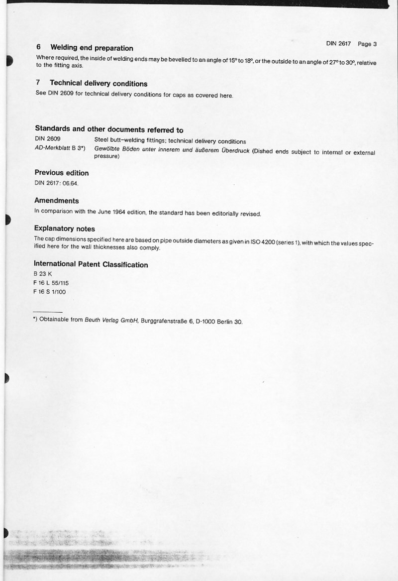
6 Welding end preparation
Where required, the inside of welding ends may be bevelled to an angle of 15° to 18°, or the outside to an angle of 27° to 30°, relative to the fitting axis.
7 Technical delivery conditions
See DIN 2609 for technical delivery conditions for caps as covered here.
Standards and other documents referred to
| DIN 2609 | Steel butt-welding fittings; technical delivery conditions |
| AD-Merkblatt B 3*) | Gewölbte Böden unter innerem und äußerem Überdruck (Dished ends subject to internal or external pressure) |
Previous edition
DIN 2617: 06.64.
Amendments
In comparison with the June 1964 edition, the standard has been editorially revised.
Explanatory notes
The cap dimensions specified here are based on pipe outside diameters as given in ISO 4200 (series 1), with which the values specified here for the wall thicknesses also comply.
International Patent Classification
B 23 K
F 16 L 55/115
F 16 S 1/100
*) Obtainable from Beuth Verlag GmbH, Burggrafenstraße 6, D-1000 Berlin 30.
3
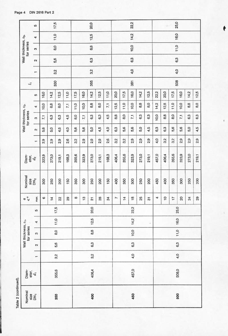
Table 2 (continued).
| Nominal size DN1 | Diameter, d1 | Wall thickness, s1, for series | αxo max. | Nominal size DN2 | Diameter, d2 | Wall thickness, s2, for series | l1 | Wall thickness, s3, for series | ||||||||||||
|---|---|---|---|---|---|---|---|---|---|---|---|---|---|---|---|---|---|---|---|---|
| 1 | 2 | 3 | 4 | 5 | 1 | 2 | 3 | 4 | 5 | 1 | 2 | 3 | 4 | 5 | ||||||
| 350 | 355,6 | 3,2 | 5,6 | 8,0 | 11,0 | 17,5 | 6 | 300 | 323,9 | 2,9 | 5,6 | 7,1 | 10,0 | 16,0 | 330 | 3,2 | 5,6 | 8,0 | 11,0 | 17,5 |
| 14 | 250 | 273,0 | 2,9 | 5,0 | 6,3 | 8,8 | 14,2 | |||||||||||||
| 22 | 200 | 219,1 | 2,9 | 4,5 | 6,3 | 8,0 | 12,5 | |||||||||||||
| 29 | 150 | 168,3 | 2,6 | 4,0 | 4,5 | 7,1 | 11,0 | |||||||||||||
| 8 | 350 | 355,6 | 3,2 | 5,6 | 8,0 | 11,0 | 17,5 | |||||||||||||
| 400 | 406,4 | 3,2 | 6,3 | 8,8 | 12,5 | 20,0 | 13 | 300 | 323,9 | 2,9 | 5,6 | 7,1 | 10,0 | 16,0 | 355 | 3,2 | 6,3 | 8,8 | 12,5 | 20,0 |
| 21 | 250 | 273,0 | 2,9 | 5,0 | 6,3 | 8,8 | 14,2 | |||||||||||||
| 28 | 200 | 219,1 | 2,9 | 4,5 | 6,3 | 8,0 | 12,5 | |||||||||||||
| 34 | 150 | 168,3 | 2,6 | 4,0 | 4,5 | 7,1 | 11,0 | |||||||||||||
| 7 | 400 | 406,4 | 3,2 | 6,3 | 8,8 | 12,5 | 20,0 | |||||||||||||
| 450 | 457,0 | 4,0 | 6,3 | 10,0 | 14,2 | 22,2 | 14 | 350 | 355,6 | 3,2 | 5,6 | 8,0 | 11,0 | 17,5 | 381 | 4,0 | 6,3 | 10,0 | 14,2 | 22,2 |
| 18 | 300 | 323,9 | 2,9 | 5,6 | 7,1 | 10,0 | 16,0 | |||||||||||||
| 25 | 250 | 273,0 | 2,9 | 5,0 | 6,3 | 8,8 | 14,2 | |||||||||||||
| 31 | 200 | 219,1 | 2,9 | 4,5 | 6,3 | 8,0 | 12,5 | |||||||||||||
| 4 | 450 | 457,0 | 4,0 | 6,3 | 10,0 | 14,2 | 22,2 | |||||||||||||
| 500 | 508,0 | 4,0 | 6,3 | 11,0 | 16,0 | 25,0 | 10 | 400 | 406,4 | 3,2 | 6,3 | 8,8 | 12,5 | 20,0 | 508 | 4,0 | 6,3 | 11,0 | 16,0 | 25,0 |
| 17 | 350 | 355,6 | 3,2 | 5,6 | 8,0 | 11,0 | 17,5 | |||||||||||||
| 20 | 300 | 323,9 | 2,9 | 5,6 | 7,1 | 10,0 | 16,0 | |||||||||||||
| 24 | 250 | 273,0 | 2,9 | 5,0 | 6,3 | 8,8 | 14,2 | |||||||||||||
| 29 | 200 | 219,1 | 2,9 | 4,5 | 6,3 | 8,0 | 12,5 | |||||||||||||
4
Table 2 (continued)
| Nominal size DN1 | Diameter, d1 | Wall thickness, s1, for series | αmax | χ° | Nominal size DN2 | Diameter, d2 | Wall thickness, s2, for series | l1 | Wall thickness, s3, for series | ||||||||||||
|---|---|---|---|---|---|---|---|---|---|---|---|---|---|---|---|---|---|---|---|---|---|
| 1 | 2 | 3 | 4 | 5 | 1 | 2 | 3 | 4 | 5 | 1 | 2 | 3 | 4 | 5 | |||||||
| 600 | 610,0 | 5,0 | 6,3 | 12,5 | 17,5 | 30,0 | 10 | 500 | 508,0 | 4,0 | 6,3 | 11,0 | 16,0 | 25,0 | 508 | 5,0 | 6,3 | 12,5 | 17,5 | 30 | |
| 15 | 450 | 457,0 | 4,0 | 6,3 | 10,0 | 14,2 | 22,2 | ||||||||||||||
| 21 | 400 | 406,4 | 3,2 | 6,3 | 8,8 | 12,5 | 20,0 | ||||||||||||||
| 26 | 350 | 355,6 | 3,2 | 5,6 | 8,0 | 11,0 | 17,5 | ||||||||||||||
| 29 | 300 | 323,9 | 2,9 | 5,6 | 7,1 | 10,0 | 16,0 | ||||||||||||||
| 700 | 711,0 | 5,0 | 7,1 | 12,5 | 20,0 | 32,0 | 33 | 250 | 273,0 | 2,9 | 5,0 | 6,3 | 8,8 | 14,2 | 610 | 5,0 | 7,1 | 12,5 | 20,0 | 32 | |
| 10 | 600 | 610,0 | 5,0 | 6,3 | 12,5 | 17,5 | 30,0 | ||||||||||||||
| 15 | 500 | 508,0 | 4,0 | 6,3 | 11,0 | 16,0 | 25,0 | ||||||||||||||
| 20 | 450 | 457,0 | 4,0 | 6,3 | 10,0 | 14,2 | 22,2 | ||||||||||||||
| 25 | 400 | 406,4 | 3,2 | 6,3 | 8,8 | 12,5 | 20,0 | ||||||||||||||
| 800 | 813,0 | 5,6 | 8,0 | 12,5 | 22,2 | 36,0 | 30 | 350 | 355,6 | 3,2 | 5,6 | 8,0 | 11,0 | 17,5 | 610 | 5,6 | 8,0 | 12,5 | 22,2 | 36 | |
| 33 | 300 | 323,9 | 2,9 | 5,6 | 7,1 | 10,0 | 16,0 | ||||||||||||||
| 10 | 700 | 711,0 | 5,0 | 7,1 | 12,5 | 20,0 | 32,0 | ||||||||||||||
| 15 | 600 | 610,0 | 5,0 | 6,3 | 12,5 | 17,5 | 30,0 | ||||||||||||||
| 20 | 500 | 508,0 | 4,0 | 6,3 | 11,0 | 16,0 | 25,0 | ||||||||||||||
| 900 | 914,0 | 6,3 | 10,0 | 12,5 | 25,0 | 40,0 | 25 | 450 | 457,0 | 4,0 | 6,3 | 10,0 | 14,2 | 22,2 | 610 | 6,3 | 10,0 | 12,5 | 25,0 | 40 | |
| 30 | 400 | 406,4 | 3,2 | 6,3 | 8,8 | 12,5 | 20,0 | ||||||||||||||
| 35 | 350 | 355,6 | 3,2 | 5,6 | 8,0 | 11,0 | 17,5 | ||||||||||||||
| 10 | 800 | 813,0 | 5,6 | 8,0 | 12,5 | 22,2 | 36,0 | ||||||||||||||
| 15 | 700 | 711,0 | 5,0 | 7,1 | 12,5 | 20,0 | 32,0 | ||||||||||||||
| 20 | 600 | 610,0 | 5,0 | 6,3 | 12,5 | 17,5 | 30,0 | ||||||||||||||
| 25 | 500 | 508,0 | 4,0 | 6,3 | 11,0 | 16,0 | 25,0 | ||||||||||||||
| 30 | 450 | 457,0 | 4,0 | 6,3 | 10,0 | 14,2 | 22,2 | ||||||||||||||
| 35 | 400 | 406,4 | 3,2 | 6,3 | 8,8 | 12,5 | 20,0 | ||||||||||||||
5
Table 2 (concluded).
| Nominal size DN1 | Diameter, d1 | Wall thickness, s1, for series | αmax | Nominal size DN2 | Diameter, d2 | Wall thickness, s2, for series | l1 | Wall thickness, s3, for series | ||||||||||||
|---|---|---|---|---|---|---|---|---|---|---|---|---|---|---|---|---|---|---|---|---|
| 1 | 2 | 3 | 4 | 5 | 1 | 2 | 3 | 4 | 5 | 1 | 2 | 3 | 4 | 5 | ||||||
| 1000 | 1016,0 | 6,3 | 10,0 | 12,5 | 28,0 | 45,0 | 10 | 900 | 914,0 | 6,3 | 10,0 | 12,5 | 25,0 | 40,0 | 610 | 6,3 | 28,0 | 45 | ||
| 1200 | 1220,0 | 6,3 | 12,5 | - | - | - | 15 | 800 | 813,0 | 5,6 | 8,0 | 12,5 | 22,2 | 36,0 | 6,4 | 28,0 | 45 | |||
| 20 | 700 | 711,0 | 5,0 | 7,1 | 12,5 | 20,0 | 32,0 | 6,4 | 10,0 | 12,5 | ||||||||||
| 25 | 600 | 610,0 | 5,0 | 6,3 | 12,5 | 17,5 | 30,0 | 711 | 6,3 | 1,25 | - | - | - | |||||||
| 30 | 500 | 508,0 | 4,0 | 6,3 | 11,0 | 16,0 | 25,0 | 6,4 | 12,5 | - | - | - | ||||||||
| 35 | 450 | 457,0 | 4,0 | 6,3 | 10,0 | 14,2 | 22,2 | 6,6 | 12,5 | - | - | - | ||||||||
| 10 | 1000 | 1016,0 | 6,3 | 10,0 | - | - | - | 15 | 900 | 914,0 | 6,3 | 10,0 | - | - | - | |||||
| 20 | 800 | 813,0 | 5,6 | 8,0 | - | - | - | 25 | 700 | 711,0 | 5,0 | 7,1 | - | - | - | |||||
| 30 | 600 | 610,0 | 5,0 | 6,3 | - | - | - | |||||||||||||
A dash in a box indicates a size that has not been standardized.
6
预览内容由文件识别整理,表格、公式及文字请以原始文件为准。
原文图片预览
PAGE IMAGES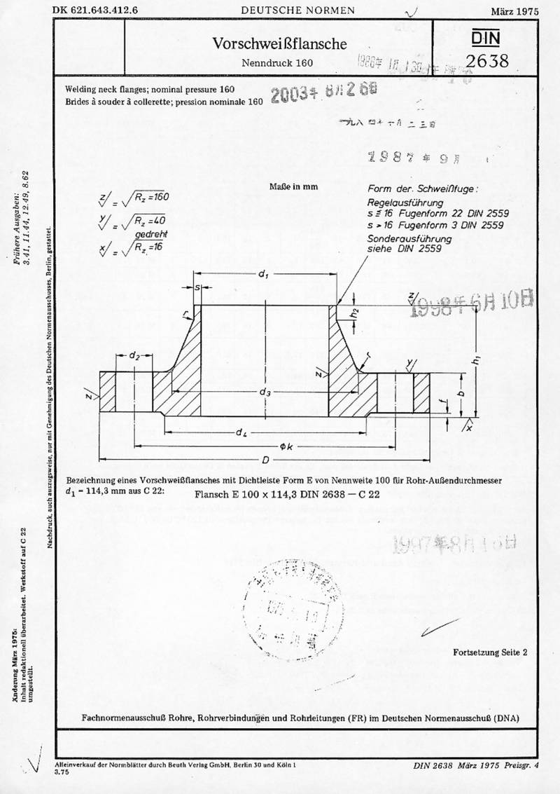
下载标准文件
DIN 2638
英语 · PDF · 6 页 · 868.04 KB